EasyManuals Logo

Tektronix 2465B Service Manual

Tektronix 2465B
536 pages
To Next Page IconTo Next Page
To Previous Page IconTo Previous Page
Page #529 background imageLoading...
Page #529 background image
Tektronix
®
COMMTTTED
TO
EXCELLENCE
MANUAL CHANGE INFORMATION
Date:
30 JAN 93 change Reference: M72666 REV1
Product: 2465B/2467B Service
Manual Part No.:
070-6863-00
DESCRIPTION
Product Group 38
EFFECTIVE SERIAL NUMBERS: 2465B B053089 and above
EFFECTIVE SERIAL NUMBERS: 2467B B050557 and above
BOARD CHANGES
A1 MAIN BOARD
Add capacitor
C511,
teepeed across
R511
(location 3J).
DIAGRAM
CHANGES
o<
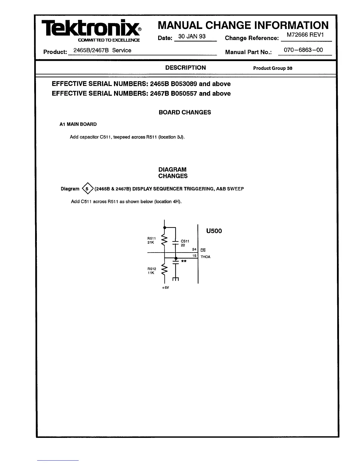
Diagram <^5 > (2465B & 2467B) DISPLAY SEQUENCER TRIGGERING, A&B SWEEP
Add C511 across
R511
as shown below (location 4H).
R511 _
21K <> -*~
C511
22
R512
11K
U500
DS
THOA
+5V

Table of Contents

Other manuals for Tektronix 2465B

Questions and Answers:

Question and Answer IconNeed help?

Do you have a question about the Tektronix 2465B and is the answer not in the manual?

Tektronix 2465B Specifications

General IconGeneral
Bandwidth400 MHz
Channels4
Vertical Sensitivity2 mV/div to 5 V/div
Maximum Input Voltage400 V (DC + peak AC)
DisplayCRT
Trigger ModesAuto, Normal, Single
Time Base Range500 ps/div to 0.5 s/div
Rise Time875 ps
Power Supply48 to 440 Hz
Dimensions495 mm

Related product manuals