Specification—2465B/2467B Service
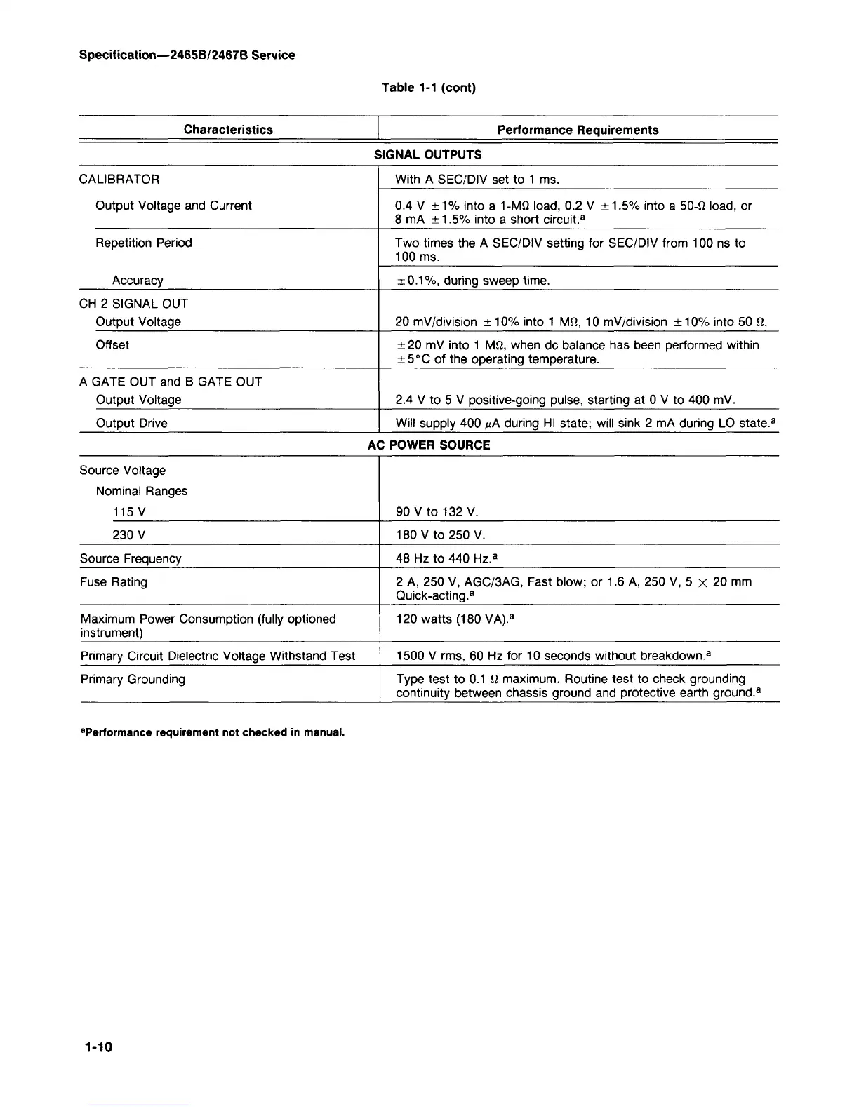
Table 1-1 (cont)
Characteristics Performance Requirements
SIGNAL OUTPUTS
CALIBRATOR
Output Voltage and Current
Repetition Period
Accuracy
CH 2 SIGNAL OUT
Output Voltage
Offset
A GATE OUT and B GATE OUT
Output Voltage
Output Drive
With A SEC/DIV set to 1 ms.
0.4 V ±1% into a 1-Mfi
load,
0.2 V ±1.5% into a 50-fi
load,
or
8 mA ±1.5% into a short circuit.
3
Two times the A SEC/DIV setting for SEC/DIV from 100 ns to
100 ms.
±0.1%,
during sweep time.
20 mV/division ±10% into 1 Mil, 10 mV/division ±10% into 50 il.
± 20 mV into 1 Mil, when dc balance has been performed within
±5°C of the operating temperature.
2.4 V to 5 V positive-going pulse, starting at 0 V to 400 mV.
Will supply 400 ^A during HI state; will sink 2 mA during LO state.
3
AC POWER SOURCE
Source Voltage
Nominal Ranges
115 V
230 V
Source Frequency
Fuse Rating
Maximum Power Consumption (fully optioned
instrument)
Primary Circuit Dielectric Voltage Withstand Test
Primary Grounding
90 V to 132 V.
180 V to 250 V.
48 Hz to 440 Hz.
3
2 A, 250 V, AGC/3AG, Fast blow; or 1.6 A, 250 V, 5 x 20 mm
Quick-acting.
3
120 watts (180 VA).
a
1500 V rms, 60 Hz for 10 seconds without breakdown.
3
Type test to 0.1 il maximum. Routine test to check grounding
continuity between chassis ground and protective earth ground.
3
"Performance requirement not checked in manual.
1-10