2465B/2467B Service
TEST WAVEFORM SETUP INFORMATION
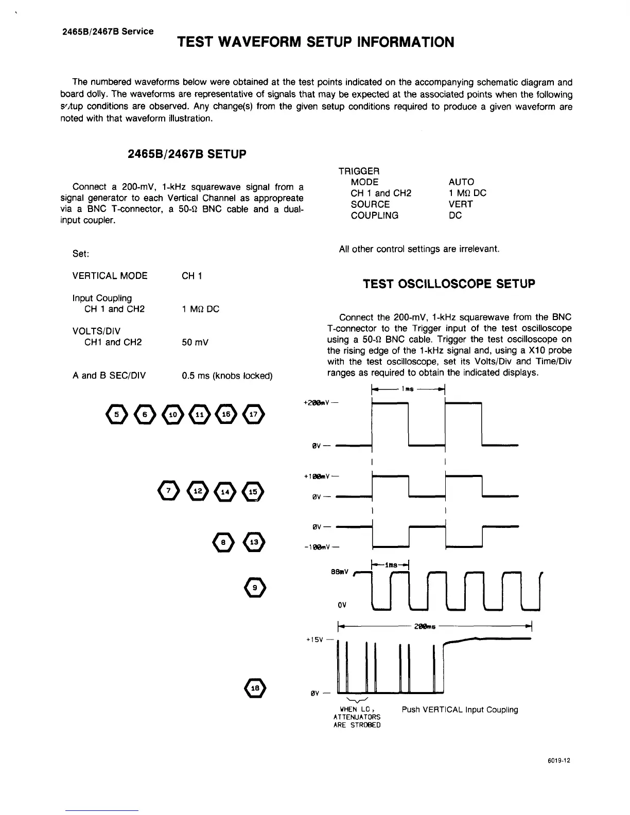
The numbered waveforms below were obtained at the test points indicated on the accompanying schematic diagram and
board dolly. The waveforms are representative of signals that may be expected at the associated points when the following
s';tup conditions are observed. Any change(s) from the given setup conditions required to produce a given waveform are
noted with that waveform illustration.
2465B/2467B SETUP
Connect
a
200-mV, 1-kHz squarewave signal from
a
signal generator to each Vertical Channel as appropreate
via
a
BNC T-connector,
a
50-fi BNC cable and
a
dual-
input coupler.
MODE
CH 1 and CH2
SOURCE
COUPLING
AUTO
1 Mfi DC
VERT
DC
Set:
VERTICAL MODE
Input Coupling
CH 1 and CH2
VOLTS/DIV
CH1 and CH2
A and B SEC/DIV
CH 1
1 MfiDC
50 mV
0.5 ms (knobs locked)
000000
All other control settings are irrelevant.
TEST OSCILLOSCOPE SETUP
Connect the 200-mV, 1-kHz squarewave from the BNC
T-connector to the Trigger input of the test oscilloscope
using a 50-fi BNC cable. Trigger the test oscilloscope on
the rising edge of the 1-kHz signal and, using a X10 probe
with the test oscilloscope, set its Volts/Div and Time/Div
ranges as required to obtain the indicated displays.
+288mV —
0V —
1ms
0000
+100nV-
0V-
00
0
0
0V —
-100tnV-
88mv
0V
-ims-«
LTLrUTJli
208ms
+ I5V —
0V
U_l
WHEN
LO,
ATTENUATORS
ARE
STROBED
Push VERTICAL Input Coupling
6019-12