Theory of Operation—2465B/2467B Service
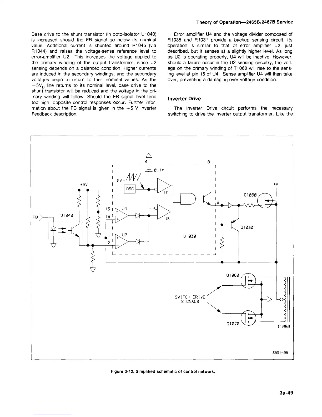
Base drive to the shunt transistor (in opto-isolator U1040)
is increased should the FB signal go below its nominal
value.
Additional current is shunted around R1045 (via
R1044) and raises the voltage-sense reference level to
error-amplifier U2. This increases the voltage applied to
the primary winding of the output transformer, since U2
sensing depends on a balanced condition. Higher currents
are induced in the secondary windings, and the secondary
voltages begin to return to their nominal values. As the
+ 5V
D
line returns to its nominal level, base drive to the
shunt transistor will be reduced and the voltage in the
pri-
mary winding will follow. Should the FB signal level tend
too
high,
opposite control responses occur. Further infor-
mation about the FB signal is given in the +5 V Inverter
Feedback description.
Error amplifier U4 and the voltage divider composed of
R1035 and R1031 provide a backup sensing circuit. Its
operation is similar to that of error amplifier U2, just
described,
but it senses at a slightly higher level. As long
as U2 is operating properly, U4 will be inactive. However,
should a failure occur in the U2 sensing circuitry, the volt-
age on the primary winding of T1060 will rise to the sens-
ing level at pin 15 of U4. Sense amplifier U4 will then take
over, preventing a damaging over-voltage condition.
Inverter Drive
The Inverter Drive circuit performs the necessary
switching to drive the inverter output transformer. Like the
A
<-5V
0V
_/VW
FB
in 040
osc
\
d^
0.1V
Q1050
111
030
i / 4i
Q1030
Q1060
SWITCH DRIVE
SIGNALS
«H>
Q1070 \JZ/
T1060
3831-08
Figure 3-12. Simplified schematic of control network.
3a-49