a. Set Clocked Data to Yes.
b. Tap the Clock Source field and select the source for the parallel bus clock signal.
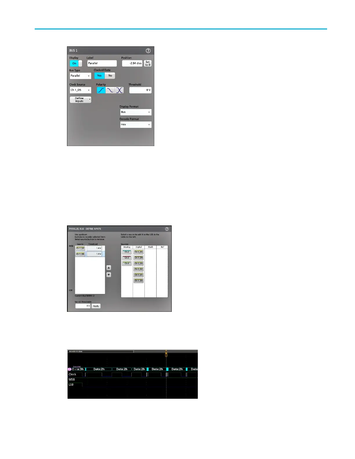
c. Tap the Polarity and Threshold controls and set the clock signal transition to detect and threshold level, respectively.
3. Tap Define Inputs and select the signal sources for the parallel bus. Signal sources can be analog, digital, math, or
reference. Tap a signal in the Sources list to add it to the bus list on the left.
The bus waveform updates as you make changes on the configuration menu. Tap the + symbol next to the waveform
handle to turn on and off showing the signals associated with the bus waveform.
4. Use the rest of the fields and controls in the configuration menu to set up the parallel bus parameters (label, position, display
and decode formats).
Acquiring digital signals
MSO54, MSO56, MSO58, MSO58LP, MSO64 Help 115

 Loading...


