Switching Loss algorithm. Switch-Mode Power Supply (SMPS) design has three types of losses, they are Turn-On (T
on
), Turn-
off (T
off
), and Conduction loss (Cond). To achieve the maximum efficiency, losses should be reduced. This section details about
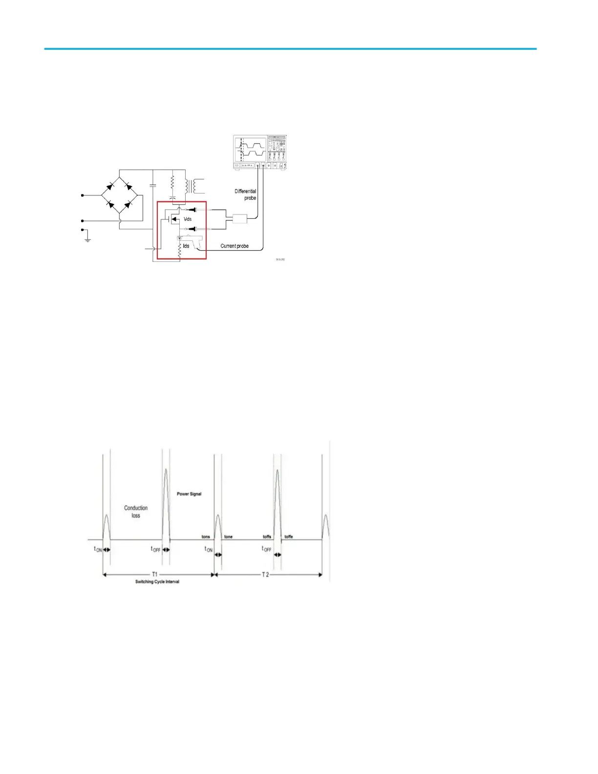
the basics of Switching Loss Analysis. A simplified SMPS schematic is shown below:
SMPS circuit diagram shows the points where switching loss can be measured. After full wave rectification, the current signal
should pass through the harmonic standard and enters for DC conversation. MOSFIT plays an important role to meet the design
of SMPS.
Regions of T
on
, T
off
, and Conduction loss (Cond) with voltage source (Vds) and current source (Ids) are shown in Switching Loss
T
on
, T
off
, and Conduction loss regions.
All the switching losses are measured on Power signal, based on Vds and Ids transition.
T
on
Loss region: When Vds starts rolling towards zero, the Ids starts to roll upward.
T
off
Loss region: When Vds starts rolling upwards, the Ids start to roll towards zero.
Conduction Loss region: The region when the Ids is high and Vds is low.
T1 is the First switching cycle.
T2 is the Second switching cycle.
■
T
on
and T
off
losses
T
on
and T
off
losses per switching cycle are computed as in the following equations:
Measurement algorithms
468 MSO54, MSO56, MSO58, MSO58LP, MSO64 Help

 Loading...


