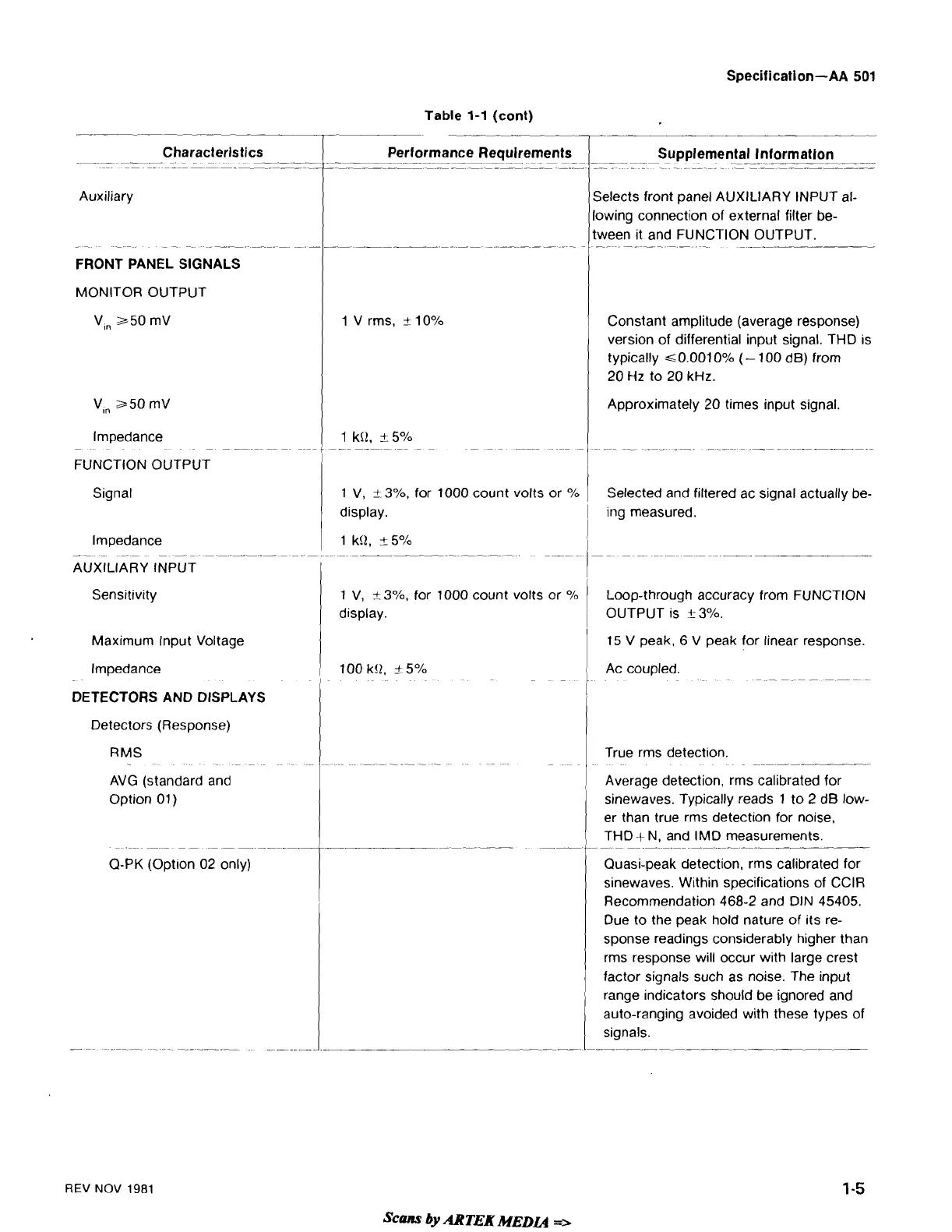
Auxiliary
-
--
-
-
-
.-
-
--
-
-
-
FRONT PANEL SIGNALS
MONITOR OUTPUT
lmpedance
FUNCTION OUTPUT
Signal
Sensitivity
Maximum
Input Voltage
lmpedance
DETECTORS AND DISPLAYS
Detectors (Response)
RMS
AVG (standard and
Option
01)
-
-
-
-
-
-
-
-
-
-
-
-.
Q-PK
(Opt~on 02 only)
Table
1-1
(cont)
-
Performance
--
-
--
Requirements
--
.
-
-
-
-
-
-
1 V rms,
k
10%
1
V,
+-
3%,
for 1000 count volts or
O/O
display.
1 V,
+-
3%, for 1000 count volts or
O/O
display.
Supplemental Information
---
-
-
.
--
-
-
--
-
---
-
-
-
-
Selects front panel AUXILIARY INPUT al-
owing connect~on of external filter be-
ween lt and FUNCTION OUTPUT.
-
-
-
-
-
-
-
-
Constant amplitude (average response)
version of differential input signal. THD is
typically
~O.OOIOO/~
(-
100 dB) from
20
Hz
to 20 kHz.
Approximately 20 times input signal.
Selected and filtered ac signal actually be-
ing measured.
Loop-through accuracy from FUNCTION
OUTPUT
IS
t
3%.
15 V peak, 6 V peak for linear response.
Ac coupled.
-
-
-
-
-
-
-
-
-
True rms detection.
-
-
Average detection, rms calibrated for
sinewaves. Typically reads 1 to 2 dB low-
er than true rms detection for noise,
THO+
N,
and IMD measurements.
-.
--
~
~
Quasi-peak detection, rms calibrated for
sinewaves. Within specifications of
CClR
Recommendation 468-2 and DIN 45405.
Due to the peak hold nature of its re-
sponse readings considerably higher than
rms response will occur with large crest
factor signals such as noise. The input
range indicators should be ignored and
auto-ranging avoided with these types of
signals.
REV
NOV
1981
Scans
by
ARTEK
MEDU
=,