Operating
Instructions-AA
501
A
Actual
transfer
/
characterlstlc
Actual Ideal
Output output output
/
lnput
'.be/
/
/
1
Input
/
/
/
/
2958-05
-
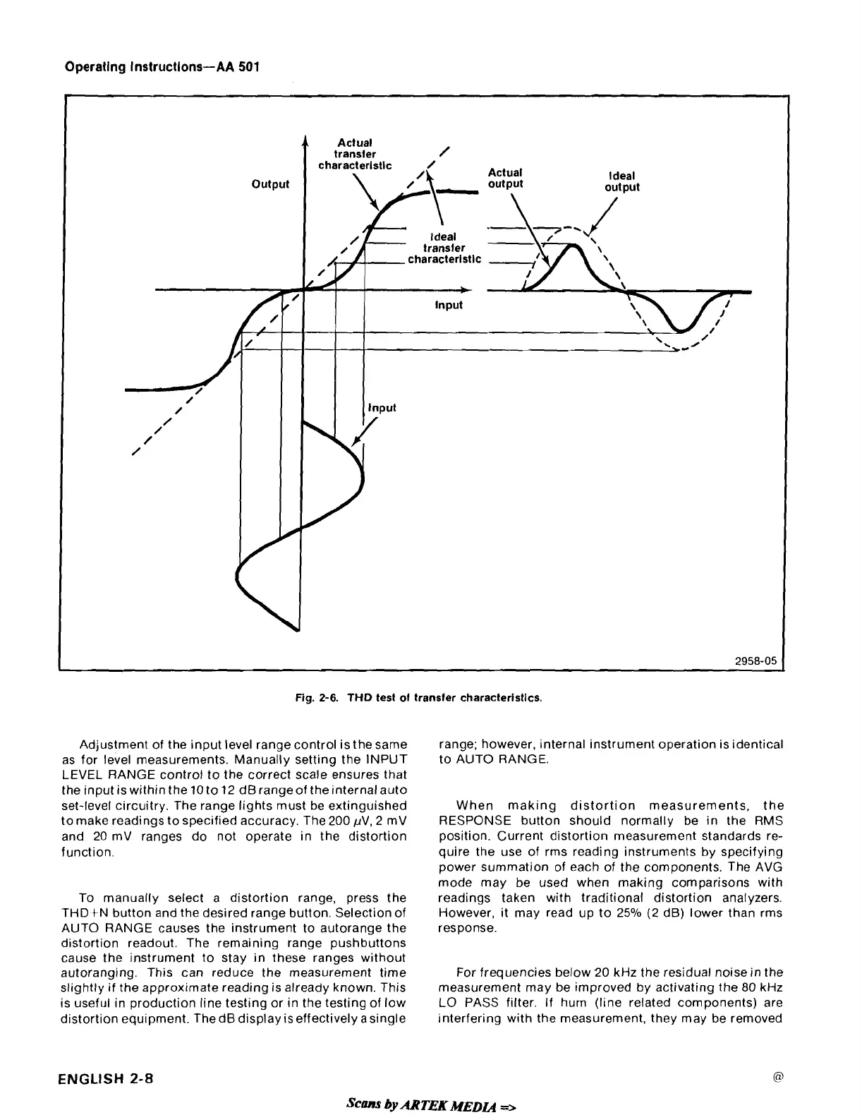
Fig.
2-6.
THD
test of transfer characterlstlcs.
Adjustment of the input level range control is the same
as for level measurements. Manually setting the INPUT
LEVEL RANGE control to the correct scale ensures that
the input is within the
10
to
12
derangeof theinternalauto
set-level circuitry. The range lights must be extinguished
to make readings to specified accuracy. The
200
pV,
2
mV
and
20
mV ranges do not operate in the distortion
function.
To manually select a distortion range, press the
THD
tN button and the desired range button. Selection of
AUTO RANGE causes the instrument to autorange the
distortion readout. The remaining range pushbuttons
cause the instrument to stay in these ranges without
autoranging. This can reduce the measurement time
slightly if the approximate reading is already known. This
is useful in production line testing or in the testing of low
distortion equipment.
ThedB display iseffectively asingle
range; however, internal instrument operation is identical
to AUTO RANGE.
When making distortion measurements, the
RESPONSE button should normally be in the RMS
position. Current distortion measurement standards re-
quire the use of rms reading instruments by specifying
power summation of each of the components. The AVG
mode may be used when making comparisons with
readings taken with traditional distortion analyzers.
However, it may read up to
25% (2
dB) lower than rms
response.
For frequencies below
'20
kHz the residual noisein the
measurement may be improved by activating the
80
kHz
LO PASS filter.
If
hum (line related components) are
interfering with the measurement, they may be removed
ENGLISH
2-8