h. Set the output amplitude of the SG
502
for a display
q. Remove all connections for the next step.
reading of
,600 (600
pV).
7.
Check Residual Total Harmonic Distortion
+
i. Change the INPUT LEVEL RANGE switch to the
Noise
200
mV position.
NOTE
j.
Turn on the SG
505
output.
Care must be taken to minimize common mode
signals appearing with signals to be analyzed. The
AA
501
and
SG
505,
used in this step, must be
k. Adjust the output amplitude of the SG
505
for a
properly installed in the same power module.
display reading of
60.0 (60
mV).
I. Press the FUNCTION THD+N pushbutton.
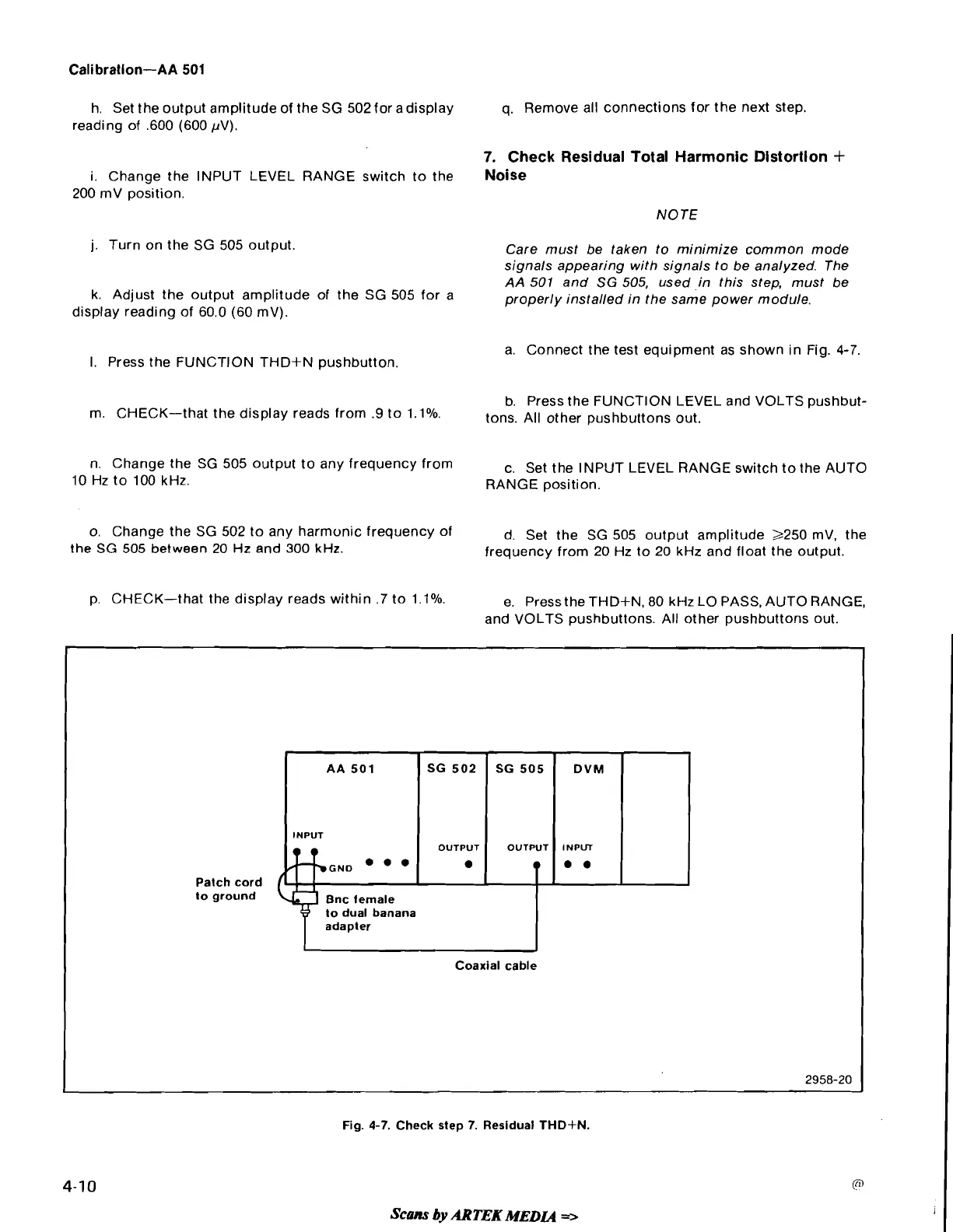
a. Connect the test equipment as shown in Fig.
4-7.
b. Press the FUNCTION LEVEL and VOLTS pushbut-
m. CHECK-that the display reads from
.9
to
l.lO/o.
tons,
~11
other pushbuttons
out.
n. Change the SG
505
output to any frequency from
c. Set the INPUT LEVEL RANGE switch to the AUTO
10
Hz to
100
kHz.
RANGE position.
o. Change the SG
502
to any harmonic frequency of
d. Set the SG
505
output amplitude
2250
mV, the
the
SG
505
between
20
Hz and
300
kHz.
frequency from
20
Hz to
20
kHz and float the output.
p. CHECK-that the display reads within
.7
to
l.lO/o.
e. Press the THD+N,
80
kHz LO PASS, AUTO RANGE,
and VOLTS pushbuttons. All other pushbuttons out.
2
1
SG
505
(
DVM
Patch cord
to ground
to dual banana
adapter
Coaxial cable
Fig.
4-7.
Check step
7.
Residual
THD-kN.
Scans
by
ARTEK
MEDLQ
-