f. CHECK-that the display reads
40.0025%.
c. Make certain the FUNCTION LEVEL, VOLTS, and
AUTO RANGE pushbuttons are pressed. All other
pushbuttons out.
g.
Press the RESPONSE pushbutton.
d. Set the output of the SG
505
to
7
kHz and turn on
h. CHECK-that the display reads
<0.0032%.
the intermodulation test signal set to
60
Hz or the output to
8
kHz and the intermodulation test signal to
250
Hz. See
the Maintenance section for jumper selection information.
i.
Release the
80
kHz LO PASS pushbutton.
e. Set the output amplitude of the
SG
505
to any value
j.
Change the output frequency of the SG
505
to any
2250
mV.
frequency from
10
Hz to
50
kHz.
f. Press the IMD pushbutton.
k. CHECK-that the display reads
<.0071°/~.
g.
CHECK-that the display reads
<0.0025°/~.
I.
Change the output frequency of the SG
505
to any
frequency from
50
kHz to
100
kHz.
h. Remove these connections for the next step.
m. CHECK-that the display reads
<O.OIOO/o.
n.
Leave this setup for the next step.
9.
Check Residual lntermodulation Distortion in the
CClF Difference Tone Test Mode (Option
01
only)
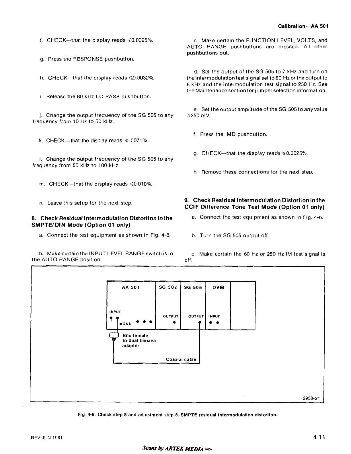
8.
Check Residual Intermodulation Distortion in the
a. Connect the test equipment as shown in Fig.
4-6.
SMPTE/DIN Mode (Option
01
only)
a. Connect the test equipment as shown in Fig.
4-8.
b. Turn the SG
505
output off
b. Make certain the INPUT
LEVEL
RANGE switch is in
c. Make certain the
60
Hz or
250
Hz IM test signal is
the AUTO RANGE
posit~on. off.
-
-
-
-
-
REV
JUN
1981
AA
501
INPUT
.GND
.
Fig.
4-8.
Check step
8
and adjustment step
8.
SMPTE
resldual intermodulation distortion.
&lns
by
ARTEK
MEDL4
r>
Bnc female
to dual banana
adapter
Coaxial cable
2958-21
SG 502
OUTPUT
SG 505
OUTPUT
DVM
INPUT
. .
 Loading...


