Cali bration-AA 501
e. Adjust the SG 502 for a 250 Hz, 6.00 mV output
signal as indicated on the AA 501 display.
c. Make certain the VOLTS, LEVEL, AUTO RANGE,
and RESPONSE pushbuttons are in. All other
pushbut-
tons out.
f. Press the 400 Hz HI PASS pushbutton.
d. Turn off both SG
505
outputs. Make certain both
outputs are floating.
g. Turn on the SG 505 output and adjust for an output
frequency of 14 kHz, and a 60
mVoutput signal amplitude
as displayed on the AA 501.
h. Press
theIMD pushbutton and releasethe400 Hz HI
PASS pushbutton.
i.
CHECK-that the display reads from 11.46% to
14.00%.
e. Adjust the SG 502 for a 250 Hz, 4.24
mV output
signal as read on the AA 501 display.
f. Press the 400 Hz HI PASS pushbutton.
g. Turn on one SG 505 output and adjust this SG 505
for an output frequency of 14 kHz, with an amplitude of
42.4
mV as displayed on the AA 501.
j.
Remove all connections for the next step.
h. Turn off this SG 505 output and turn on the
remaining SG 505 output.
11A. Check
IM
Distortion Accuracy, CClF
Difference Tone Test (alternate procedure, omit
if
step 11 is performed, Option 01 only)
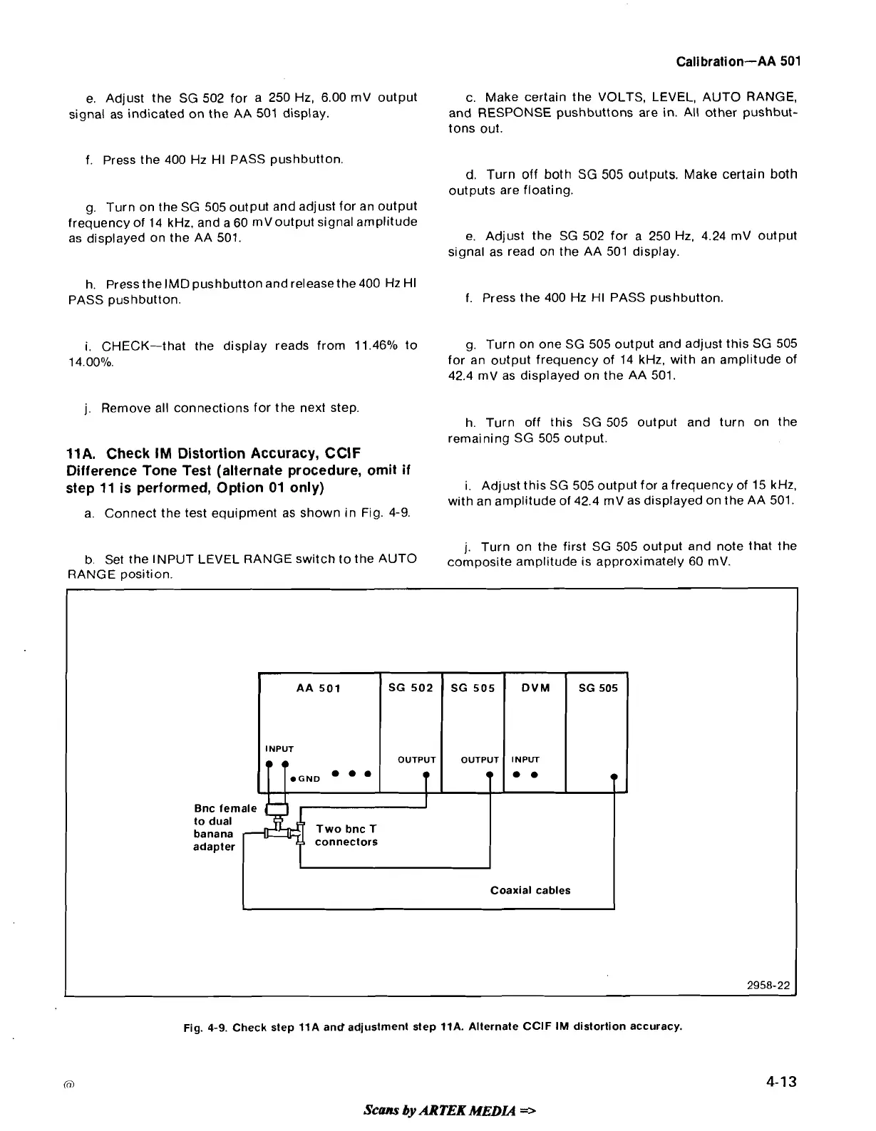
a. Connect the test equipment as shown in Fig. 4-9.
b. Set the INPUT LEVEL RANGE switch to the AUTO
RANGE position.
i. Adjust this SG 505 output for a frequency of 15 kHz,
with an amplitude of 42.4
mV as displayed on the AA 501.
j.
Turn on the first SG 505 output and note that the
composite amplitude is approximately 60
mV.
Bnc female
banana
adapter
connectors
L
AA
501
INPUT
T
1G.D
I
I
Coaxial cables
Fig.
4-9. Check step 11A andadjustment step 11A. Alternate CClF IM distortion accuracy.
Scans
by
ARTEK
MEDIA
=>
SG 502
OUTPUT
T
SG 505
OUTPUT
T
DVM
INPUT
**
SG505
9