Cali bration-AA
501
p. Raise the frequency of the SG 505 until the AA 501
f. Connect a 1
kn
0.1% resistor in parallel with the
display reads -3.0 dB.
INPUT MONITOR.
q.
CHECK-that the oscillator frequency is from
g.
CHECK-that the dvm reading is one half of the value
76
kHz to 84 kHz. noted in step e within
k
2.5%.
r. Leave these connections for the next step. h. Leave the connection tothe INPUTterminalsfor the
next step.
13.
Check INPUT MONITOR
14.
Check FUNCTION OUTPUT
a.
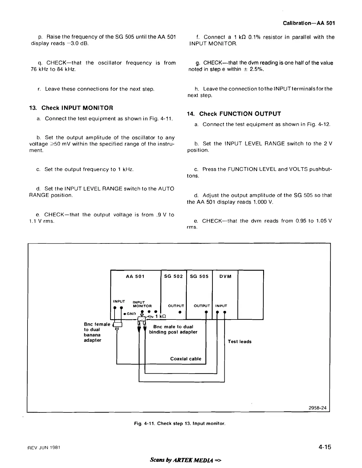
Connect the test equipment as shown in Fig. 4-1 1.
a. Connect the test equipment as shown in Fig. 4-12.
b.
Set the output amplitude of the oscillator to any
voltage
250 mV within the specified range of the instru-
b.
Set the INPUT LEVEL RANGE switch to the 2 V
ment. position.
c. Set the output frequency to 1 kHz.
c. Press the FUNCTION LEVEL and VOLTS
pushbut-
tons.
d. Set the INPUT LEVEL RANGE switch to the AUTO
RANGE position.
d. Adjust the output amplitude of the SG 505 so that
the AA 501 display reads 1.000 V.
e. CHECK-that the output voltage is from
.9 V to
1.1 V rms. e. CHECK-that the dvm reads from 0.95 to 1.05 V
rms.
Fig. 4-11. Check step 13. Input monitor.
AA
501
INPUT INPUT
MONITOR
REV
JUN
1981
Scans
by
ARTEK MEDIA
=>
DVM
INPUT
T
SG 502
OUTPUT
"
SG 505
OUTPUT
Test leads
Bnc
female
to dual
binding post adapter
2958-24
banana
adapter
Coaxial cable