Brief procedures
15. Click the Play b
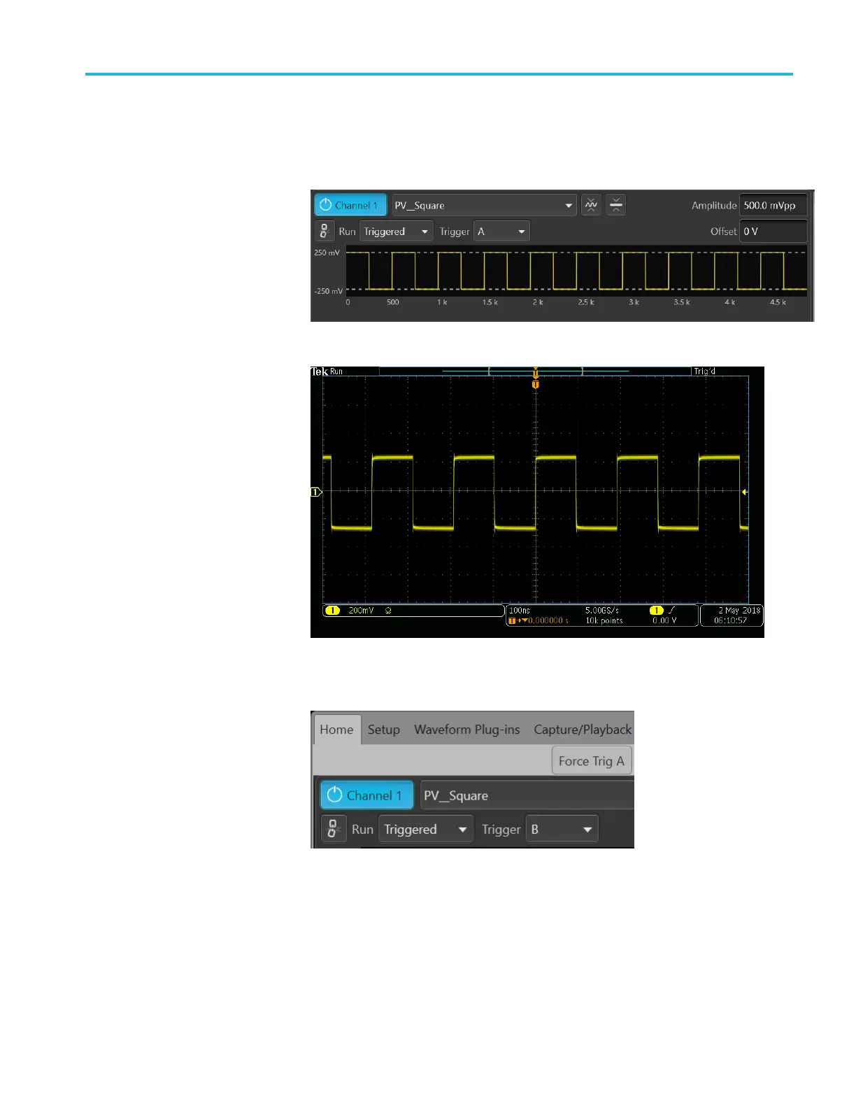
utton on-screen or on the front panel of the AWG.
16. Click the Home tab and verify that the squarewave output is displayed on
the AWG.
17. Verify that the squarewave output is displayed on the test oscilloscope.
18. Move the cable from the Trigger A input to the Trigger B input.
19. Click the Home tab and set the trigger input to B.
20
.
Ve
rify that the output is displayed on the test oscilloscope (as in step 17).
21. Press the AWG front panel All Outputs Off button (or click All Outputs Off
o
ntheHomescreen)todisable the outputs (front panel light on).
22. Disconnect the test setup.
AWG5200 Series Technical Reference 41
 Loading...


