Performance tests
7. Set the DC Bias of the AWG as shown in the first row of the following table.
(See Table 41.)
Table 41: Analog DC bias accuracy
Bias settings Accuracy limits
5 V 4.88 V to 5.12 V
0 V –20 mV to 20
mV
–5 V –5.12 V to –4.88 V
8. Measure the output voltage on the digital multimeter and note the value as
V_1.
9. Press the front panel All Outputs Off button (or click All Outputs Off on the
Home scr
een) to disable the outputs (front panel light on).
10. Measure the output voltage on the digital multimeter and note the value as
V_2 (DM
M residual voltage).
11. Verify that the voltage difference (V_1 – V_2) falls within the limits given in
the ta
ble. (See Table 41 on page 56.)
12. Repeat steps 7 through 11 for each bias setting in the table. (See Table 41
on pa
ge 56.)
13. Repeat steps 3 through 12 until all channels are checked, modifying the
ins
tructions for the channel number under test.
NOTE. This is the start of testing the optional AC Amplified output path.
If
option AC is licensed, continue with this procedure. If not, skip to step 17.
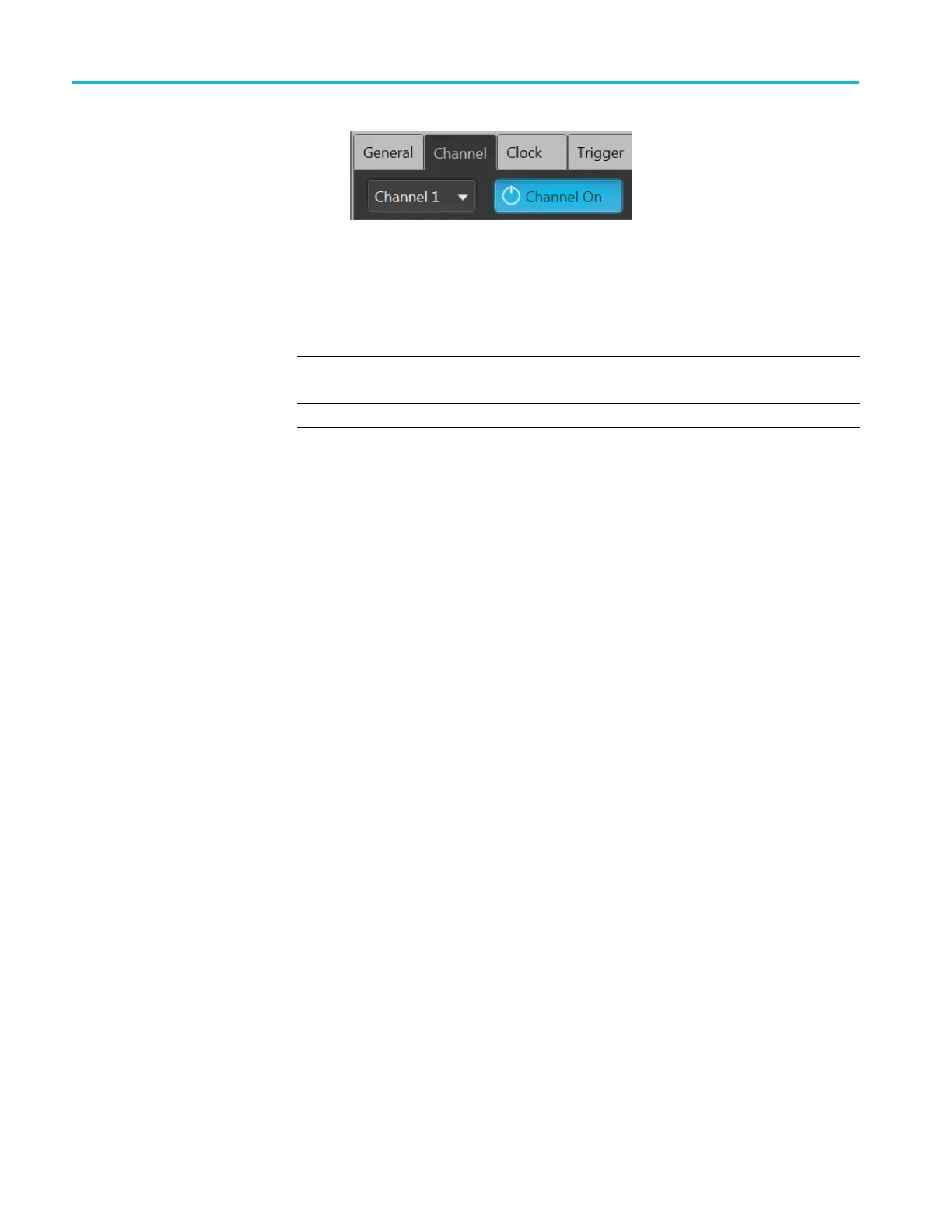
14. Click the Setup -> Channel tab and click the Output Settings tab.
a. Select Channel 1.
b. Set the Output Path to AC Amplified.
56 AWG5200 Series Technical Reference
 Loading...


