4. Select the channel to test: Push the channel button for the channel you are
currently testing. The button lights and the channel display comes on.
5. Set up the instrument:
NOTE. If the AutoSet Undo window appears, click the X.
■
Push the front panel Autoset button. This sets the horizontal and vertical
scale and vertical offset for a usable display and sets the trigger source to
the channel you are testing.
■
Pull down the Vertical menu, select Vertical Setup. Confirm that the
Ch1 Offset is about 0.0 mV (120 mV on >20 GHz models).
6. Verify that the channel is operational: Confirm that the following statements
are true.
■
Verify that the vertical scale readout and the waveform amplitude for the
channel under test. (See Table 4: Vertical settings on page 105.)
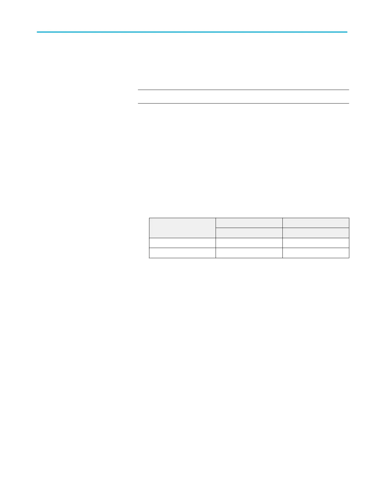
Table 4: Vertical settings
Setting <4 GHz models ≥4 GHz models
Without probe Without probe
Scale 500 mV 100 mV
Waveform amplitude 2 divisions 4 divisions
■
The front-panel vertical Position knob (for the channel you are
testing) moves the signal up and down the screen when rotated.
■
Turning the vertical Scale knob counterclockwise (for the channel
you are testing) decreases the amplitude of the waveform on-screen,
turning the knob clockwise increases the amplitude, and returning the
knob to the original scale setting returns the original amplitude for
that scale setting. (See Table 4: Vertical settings on page 105.)
7. Verify that the channel acquires in all acquisition modes: Pull down the
Horiz/Acq menu to select Horizontal/Acquisition Setup. . . . Click the
Performance verification (MSO/DPO70000C, MSO/DPO70000DX, and DPO7000C series)
MSO70000C/DX, DPO70000C/DX, DPO7000C, MSO5000/B, DPO5000/B Series 105
 Loading...

