Getting Started
SettingUpRem
ote Communications
Before setting up the instrument for remote communications using the electronic
(physical) GPIB interface, you should familiarize yourself with the following
GPIB require
ments:
A unique device address must be assigned to each device on the bus. No two
devices can
share the same device address.
No more than 15 devices can be connected to any one line.
One device should be c onnected for every 6 feet (2 meters) of cable used.
No more than 65 feet (20 meters) of cable should be used to connect devices
to a bus.
At least two-thirds of the devices on the network should be powered on while
using the network.
Connect the device s on the network in a star or linear configuration. Do not
use loop or parallel configurations.
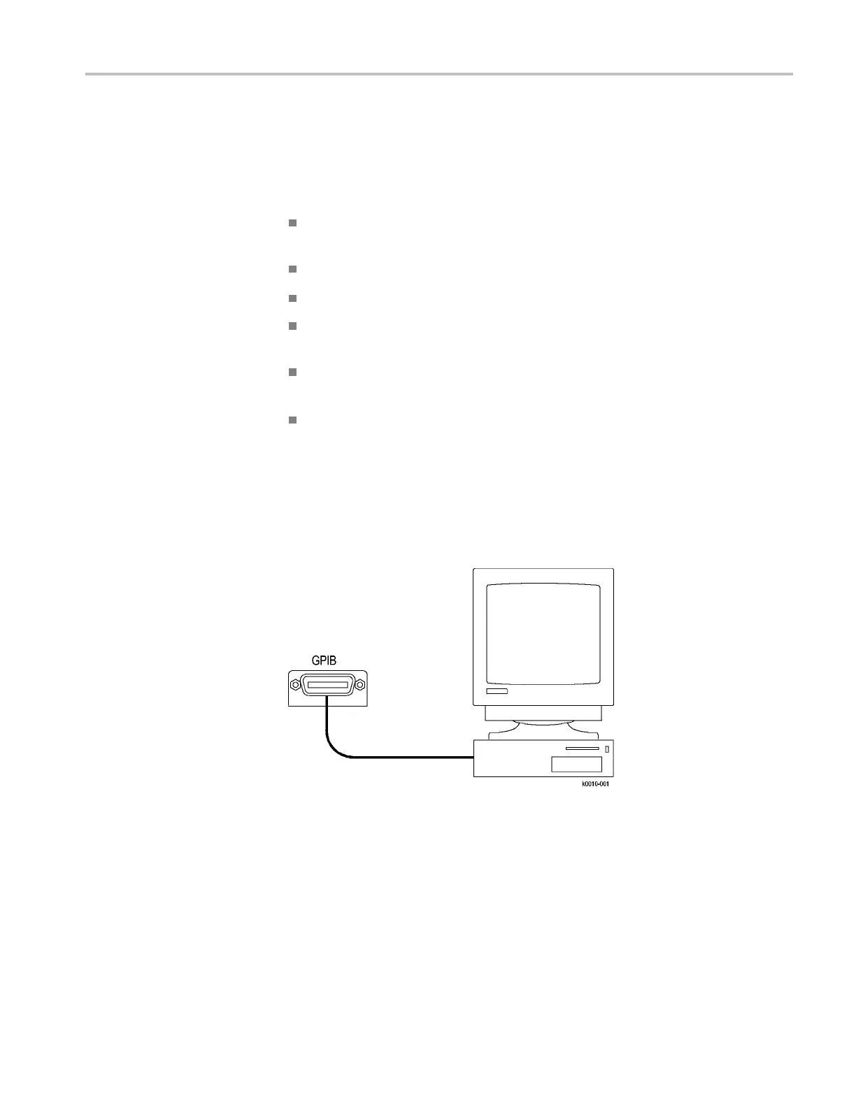
Connecting to the
Instrument
Your instrument has a 24-pin GPIB connector on its rear (side) panel. This
connector has a D-type shell and conforms to IEEE Std 488.1–1987. Attach an
IEEE Std 488.1–1987 GPIB cable to this connector and to y our controller as
shown in the following figure.
If necessary, the GPIB connectors can be stacked as shown in the figure below.
DSA/CSA/TDS8X00/B Series Programmer Manual 1-3
 Loading...