High Voltage SourceMeter Instrument User's Manual Section 5: Leakage current and in
2470-900-01 Rev. B / August 2019 5-3
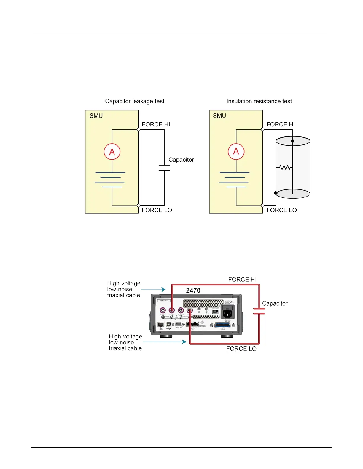
The following figure shows schematic diagrams. One shows measuring the leakage current of a
capacitor. The other shows measuring the insulator resistance between two conductors of a coaxial
cable.
Figure 21: Capacitor leakage and insulation resistance test connection schematics
The following figures show the rear-terminal connections to the device under test (DUT) for these
applications. If capacitor leakage measurements are noisy, you may need to use the high
capacitance mode or add a low leakage forward-biased diode in series with the capacitor.
Figure 22: Rear-panel connections for the leakage current test