7
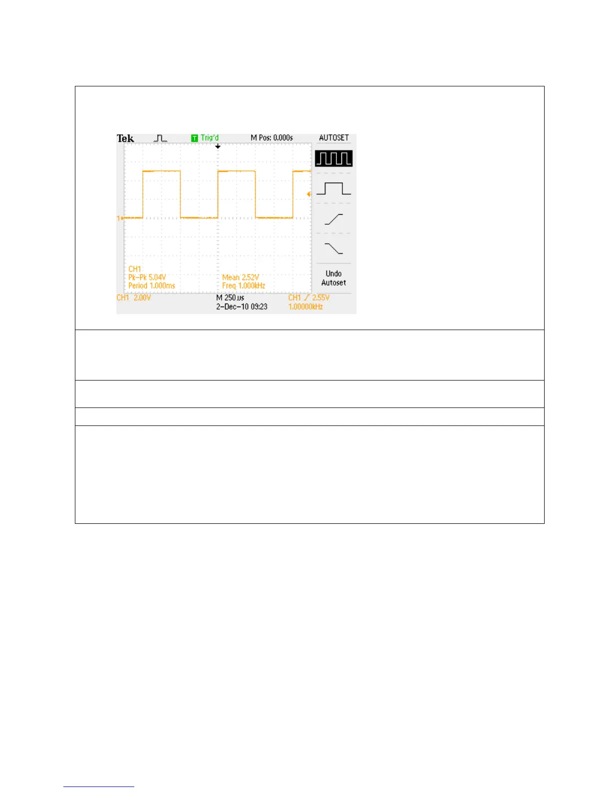
d. As can be seen on the oscilloscope screen, the square wave extends up about 2 ½ divisions on
the display graticule from the ground level indicator. Since the vertical scale factor is 2
Volts/div, this indicates the signal’s positive peak is at about +5 V.
e. One cycle of the waveform is about 4 divisions wide. The time per horizontal division is
indicated by the horizontal scale readout which in this case is 250 µsec/div (bottom center of
the display). At 250 µsec/div, the period of the signal is about 1 msec and the frequency is
about 1 kHz.
f. Finally, the trigger frequency readout indicates the channel 1 signal has a frequency of about
1 kHz as shown in the bottom right corner of the display.
Key Points to Remember
1. The input channels are color coded. Onscreen channel information is in that channel’s color,
including the waveform, ground indicator, and vertical scale factor (Volts/div).
2. The amplitude of the signal can be determined by multiplying the number of vertical divisions the
waveform spans times the vertical scale factor.
3. The signal period can be determined by multiplying the number of horizontal divisions times the
horizontal scale factor.
4. Signal frequency is calculated by dividing 1 by the signal period.

 Loading...