TDS2CM Communications Module
20
TDS 200-Series Extension Module Instructions
Processing Break Signals
When the oscilloscope
senses a break signal on the RS-232 port, it
returns DCL followed by the end of line terminator. Internally, the
oscilloscope acts as if it received a GPIB <DCL> command, causing
the oscilloscope to erase the contents of the input and output buffers
and then wait for a new command. Break signals do not change
oscilloscope settings or stored data and do not interrupt front-panel
operation or nonprogrammable functions.
If a break signal is sent in the middle of a character stream, several
characters immediately preceding or following the break can be lost.
The controller should wait until it receives the DCL and the end of
line terminator string before sending more characters.
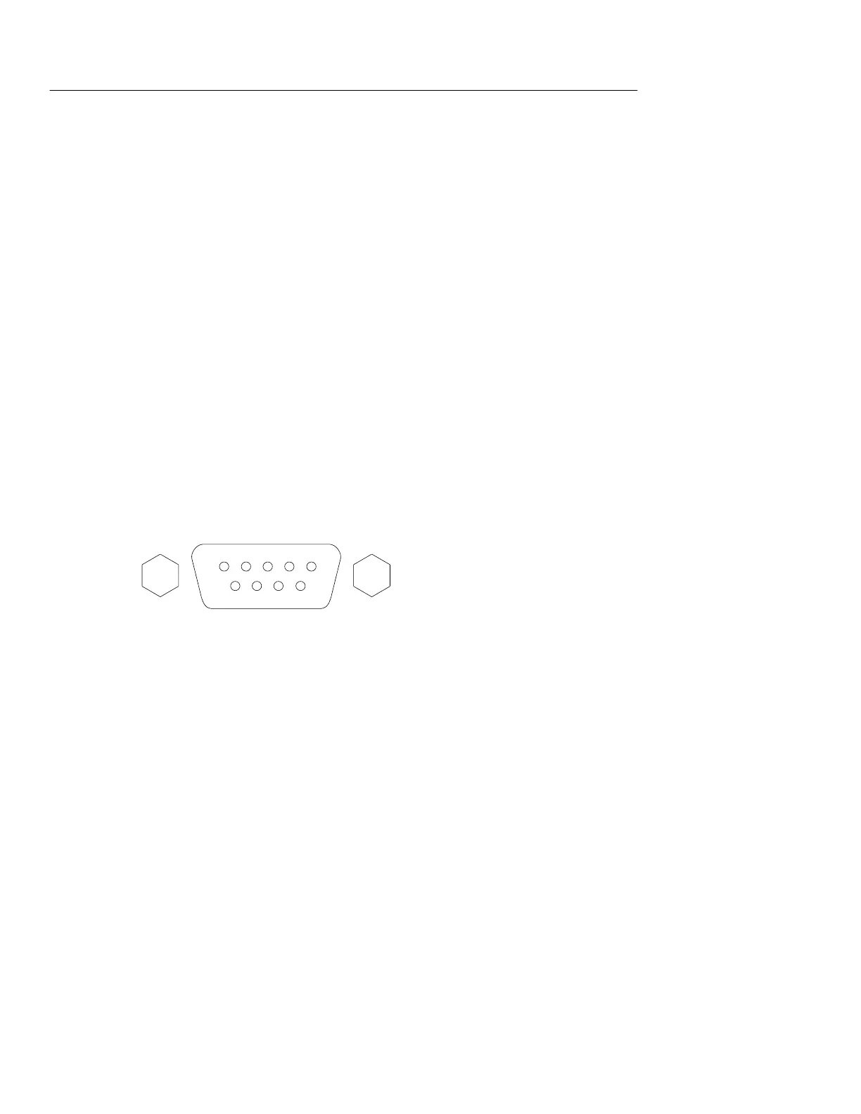
RS-232 Connector Pinout Diagram
The following diagram shows the pin numbering and signal
assignments for the TDS2CM RS-232 connector.
1 No connection
2 Receive data (RxD) (input)
3 Transmit data (TxD) (output)
4 Data terminal ready (DTR) (output)
5 Signal ground (GND)
6 Data set ready (DSR) (input)
7 Request to send (RTS) (output)
8 Clear to send (CTS) (input)
9 No connection
12345
67 89

 Loading...


