Logic Triggering
3–72
TDS 420A, TDS 430A, TDS 460A & TDS 510A User Manual
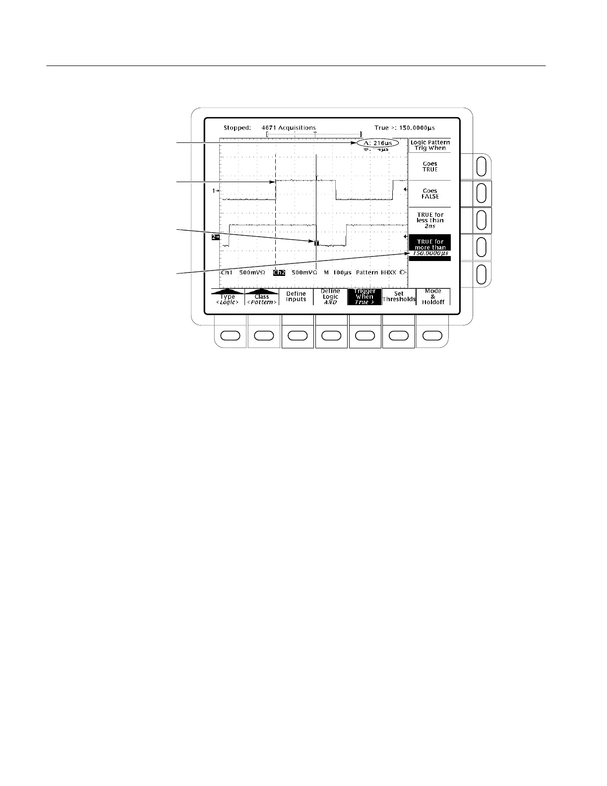
Logic Function (AND) Becomes TRUE
Logic Function Becomes FALSE and
Triggers Acquisition
Time Logic Function is TRUE
Time Logic Function Must be TRUE
Figure 3–37: Logic Trigger Menu — Time Qualified TRUE
State Operations
When you select State logic triggering, the oscilloscope uses channel 4 as a
clock for a logic circuit made from the rest of the channels. See page 3–69 for
details on operations common to both pattern and state triggers.
To set the logic state for each of the input channels (Ch1, Ch2, ...):
1. Press TRIGGER MENU
➞ Type (main) ➞ Logic (pop-up) ➞
Class
(main) ➞ State (pop-up) ➞ Define Inputs (main).
2. Choose either High (H), Low (L), or Don’t Care (X)
(side) for the first three
channels. The choices for Ch4 are rising edge and falling edge.
To choose the type of logic function you want applied to the input channels:
Press TRIGGER MENU
➞ Type (main) ➞ Logic (pop-up) ➞ Class (main) ➞
State (pop-up)
➞ Define Logic (main) ➞ AND, OR, NAND, or NOR (side).
Define Inputs
Define Logic

 Loading...


