Tutorial
2–14
TDS 420A, TDS 430A, TDS 460A & TDS 510A User Manual
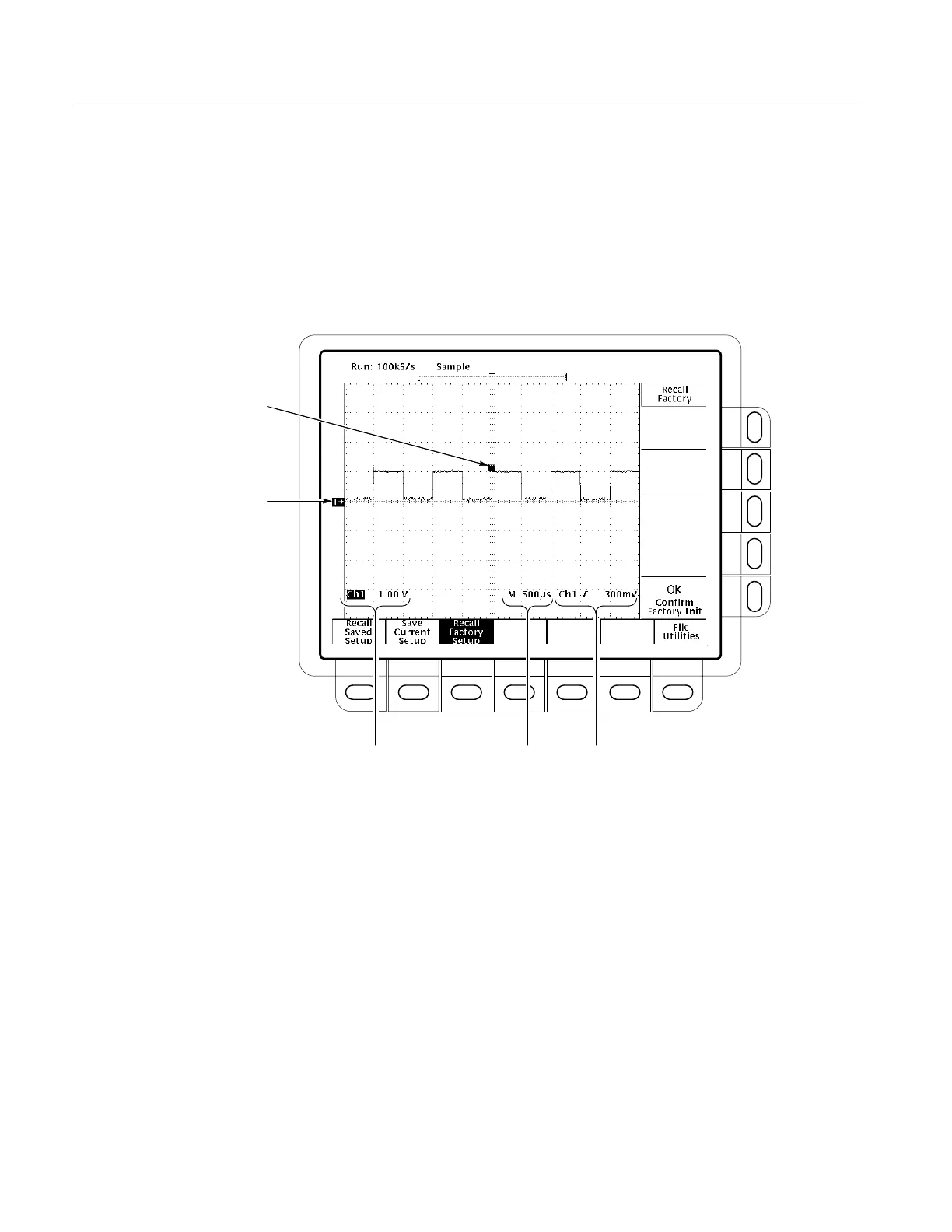
The channel readout indicates that channel 1 (Ch1) is displayed with DC
coupling. (In AC coupling, ~ appears after the volts/div readout.) The
digitizing oscilloscope always displays channel 1 at reset.
Right now, the channel, time base, and trigger readouts appear in the graticule
area because a menu is displayed. You can press the CLEAR MENU button at
any time to remove any menus and to move the readouts below the graticule.
Channel
Readout
Time Base
Readout
Channel Ground
Reference Indicator
Trigger
Readout
Trigger Position
Indicator
Figure 2–5: The Display After Factory Initialization

 Loading...


