Home
Tektronix
Test Equipment
TDS 420A
Tektronix TDS 420A User Manual
4
of 1
of 1 rating
232 pages
Give review
Manual
Specs
To Next Page
To Next Page
To Previous Page
To Previous Page
Loading...
Probe Compensation
3–90
TDS 420A, TDS 430A, TDS 460A & TDS 510A User Manual
5.
Press
SHIFT ACQUIRE MENU
➞
Mode
(main)
➞
Hi Res
(side).
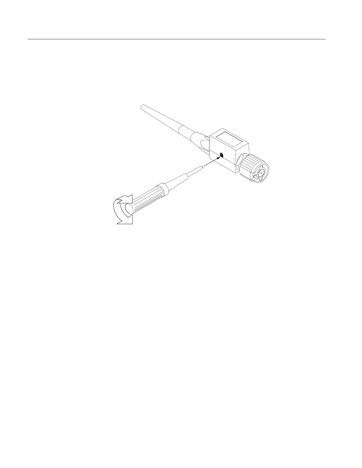
6.
Adjust the probe until you see a perfectly flat top square wave on the display
.
Figure 3–47 shows where the adjustment is located.
Figure 3–47: Probe Adjustment
140
142
Table of Contents
List of Figures
7
Table of Contents
7
Menu
14
Figure 1-1: Rear Panel Controls Used in Start up
19
Table 1-1: Fuse and Fuse Cap Part Numbers
19
Figure 1-2: ON/STBY Button
20
At a Glance Front Panel Map - Right Side (Tds 400A)
26
Saving and Recalling Setups
27
Saving and Recalling Waveforms
27
Figure 2-1: Connecting a Probe for the Examples
33
Figure 2-2: SETUP Button Location
34
Figure 2-3: the Displayed Setup Menu
34
Reset the Oscilloscope
34
Figure 2-4: SET LEVEL to 50% Button
35
Figure 2-5: the Display after Factory Initialization
36
Figure 2-6: the VERTICAL and HORIZONTAL Controls
37
Figure 2-7: TRIGGER Controls
38
Figure 2-8: AUTOSET Button Location
38
Figure 2-9: the Display after Pressing Autoset
39
Figure 2-10: Display Signals Requiring Probe Compensation
39
Figure 2-11: the Channel Buttons and Lights
40
Figure 2-12: the Vertical Main Menu and Coupling Side Menu
42
Figure 2-13: the Menus after Changing Channels
43
Figure 2-14: Measure Main Menu and Select Measurement Side
44
Figure 2-15: Four Simultaneous Measurement Readouts
45
Figure 2-16: General Purpose Knob Indicators
46
Figure 2-17: Snapshot of Channel 1
47
Figure 2-18: Save/Recall Setup Menu
49
Acquisition Modes
52
File System
52
Hardcopy
52
Help
52
Horizontal Control
52
Probe Compensation
52
Selecting Channels
52
Status
52
Vertical Control
52
Zoom
52
Figure 3-1: Initial Help Screen
54
Table 3-1: TDS 460A, TDS 430A, and TDS 420A Resolution Bits
57
Table 3-2: TDS 510A Resolution Bits
57
Figure 3-2: Acquisition Menu and Readout
59
Figure 3-3: Acquire Menu - Stop after
60
Figure 3-4: Delayed Runs after Main
62
Figure 3-5: Delayed Triggerable
62
Figure 3-6: Delayed Trigger Menu (TDS 400A Shown)
65
Figure 3-7: Status Menu - System (TDS 400A Shown)
66
Figure 3-8: Banner Display
67
Figure 3-9: Display Menu - Style
68
Figure 3-10: Trigger Point and Level Indicators
70
Table 3-3: XY Format Pairs
71
Figure 3-11: Edge Trigger Readouts
72
Figure 3-12: Record View, Trigger Position, and Trigger Level Bar Readouts
73
Table 3-4: Logic Triggers
119
Table 3-5: Measurement Definitions
124
Table 3-6: Probe Cal Status
137
Table 3-7: Pulse Trigger Definitions
142
Table A-1: International Power Cords
200
Table A-2: Standard Accessories
201
Table A-3: Optional Accessories
201
Table A-4: Compatible Probes
202
Table A-5: Accessory Software
203
Other manuals for Tektronix TDS 420A
Service Manual
288 pages
Programmer's Manual
433 pages
Reference
6 pages
4
Based on 1 rating
Ask a question
Give review
Questions and Answers:
Need help?
Do you have a question about the Tektronix TDS 420A and is the answer not in the manual?
Ask a question
Tektronix TDS 420A Specifications
General
Brand
Tektronix
Model
TDS 420A
Category
Test Equipment
Language
English
Related product manuals
Tektronix TDS 410A
291 pages
Tektronix TDS 220
120 pages
Tektronix TDS 360
65 pages
Tektronix TDS 700D
376 pages
Tektronix TDS 2012
18 pages
Tektronix TDS 520D
376 pages
Tektronix TDS 684A
303 pages
Tektronix TDS 340A
164 pages
Tektronix TDS 500D
376 pages
Tektronix TDS 520B
303 pages
Tektronix TDS 500C
352 pages
Tektronix TDS Series
394 pages