Installation Instructions
20
TDS5000B Series (Option 1R) Rackmount Kit
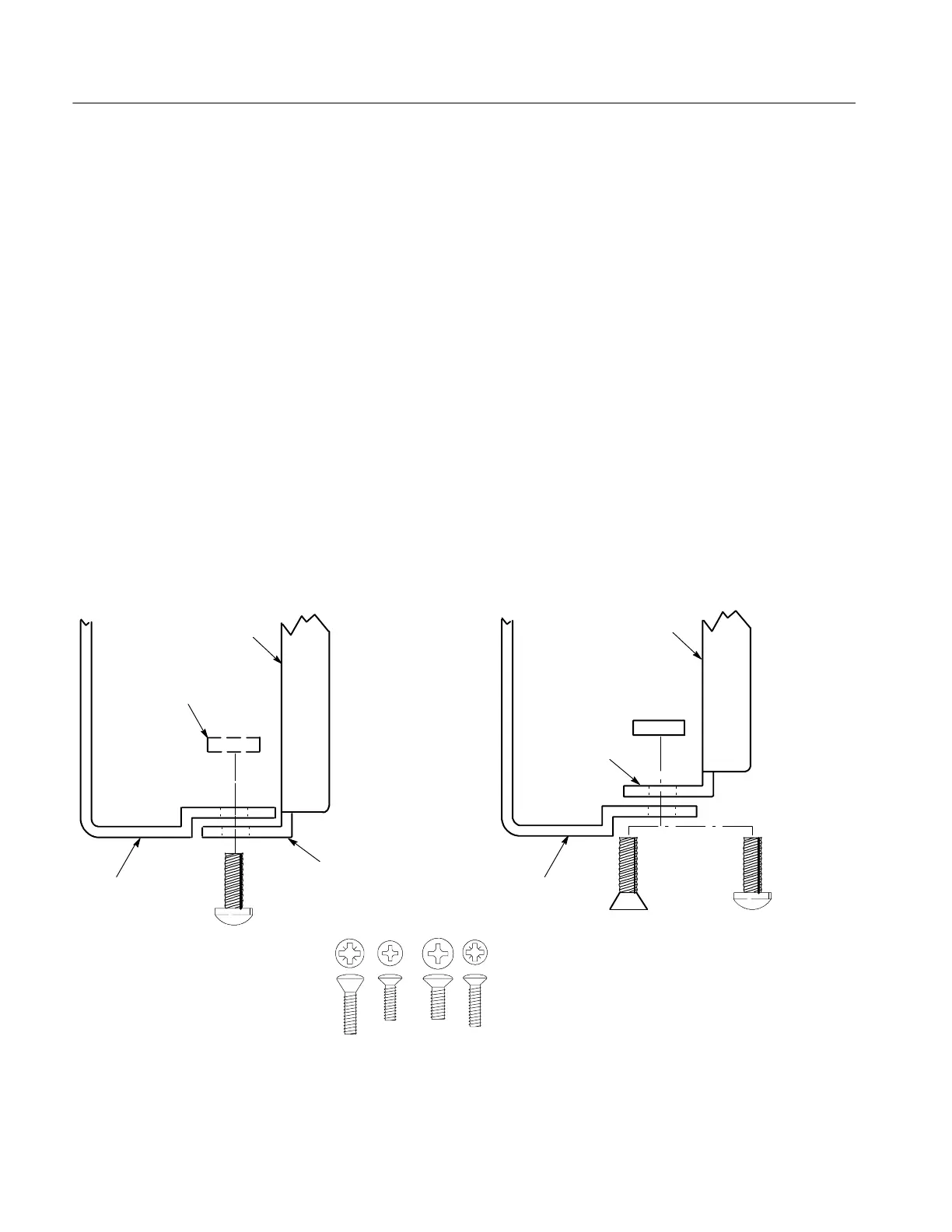
b. Select mounting method accor ding to rack type:
H To mount the slide-out tracks with their front and rear flanges
outside of the front and rear rails, use the mounting method A shown
in Figure 11 when doing substep c. Add a bar nut to the installation
only if the rails have untapped holes.
H To mount with front and rear flanges inside of rails, use the
mounting method B outlined in Figure 11. This mounting method
assumes untapped holes.
c. Install in rack: Using the method and hardware determined from substep
b, secure the right slide-out track assembly to its front and rear rails. The
screws should be fully, but lightly, seated so mounting can be adjusted
later.
d. Fix the length of the slide-out track assembly: Tighten the screws,
applying 28 inch-lbs of torque, left loose in step 1, substep c to fix the
front to rear flange spacing of the slide-out track assembly.
e. Mount the left slide-out track assembly: Repeat substeps a through d to
mount the left slide-out track assembly.
Mounting Method A Mounting Method B
Left-front rail
Use two flat-head screws if the cabinet rails have
countersunk mounting holes; otherwise use two
pan-head screws
Use a bar nut if front rails
are not tapped
10-32 Flat-head
screws (4)
10-32 Pan-head
screws (4)
10-32 Pan-head
screws (4)
Left-front rail
#10 M6 M5
English Metric
#12
Outer track
Front flange
Outer track
Front flange
Figure 11: Installation of slide-out track assemblies in rack (top view)

 Loading...


