Removal and Installation Procedures
TDS7104 & TDS7054 Service Manual
6-- 37
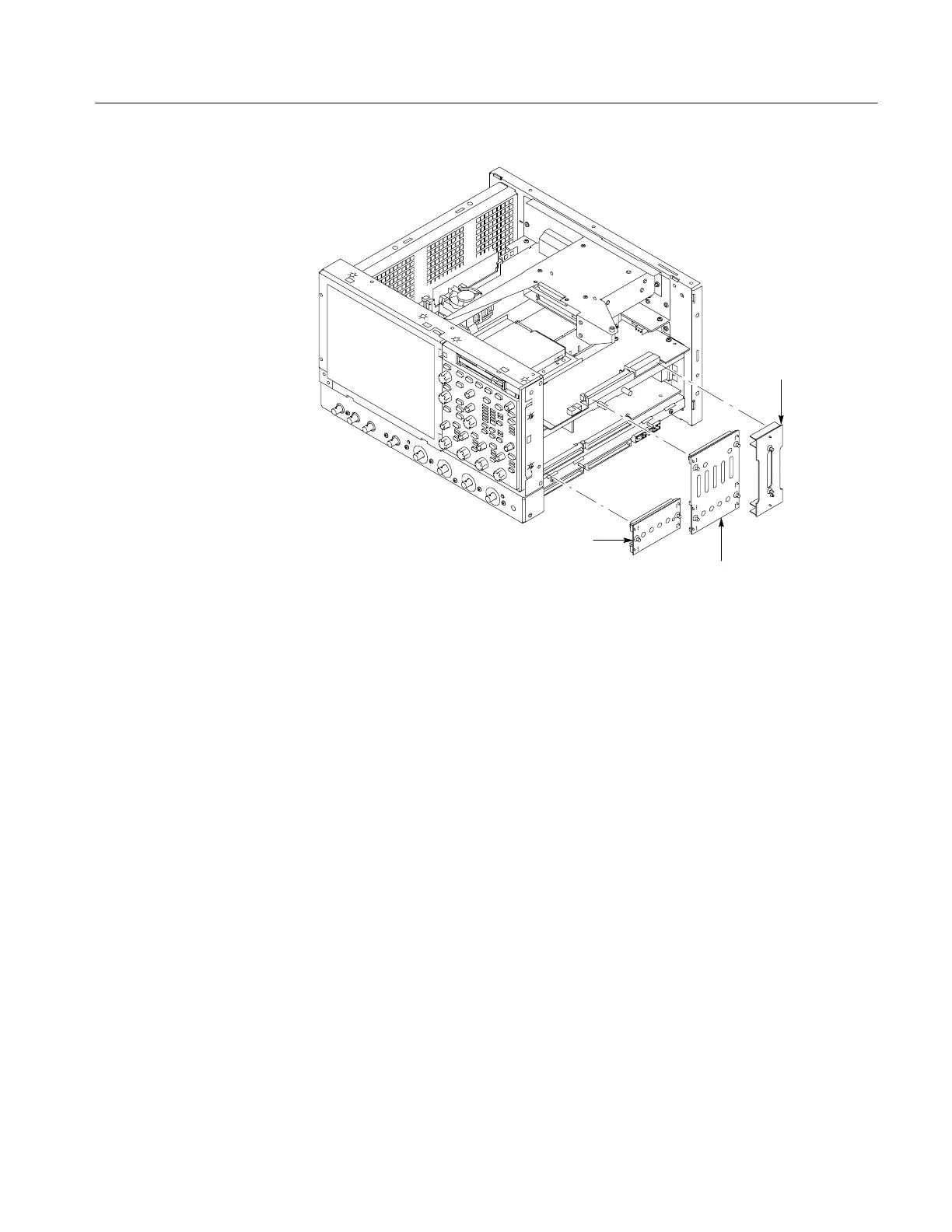
Rear power
distribution
circuit board
Front power
distribution
circuit board
PA bus
circuit board
Figure 6--22: Front and rear power distribution and PA bus boards removal
1. Assemble equipment and locate modules to be removed: Locate the modules
to be removed in the locator diagram Internal Modules, Figure 6--8,
on page 6--19. Additional modules to be Removed:
H Trim (all)
H Bottom cover
H Left and Right covers
H Front and Rear Distribution Boards and the PA bus interconnect board
2. Orient the oscilloscope: Set the oscilloscope so its bottom is down on the
work surface and its right -side is facing you.
3. Remove the low-voltage power supply: See Figure 6--23, on page 6--38.
a. Remove the two T-15 Torx screws securing the low-voltage power
supply to the right-side chassis support.
b. Remove the three T-15 Torx screws securing the low-voltage power
supply to rear chassis.
Low-Voltage Power
Supply
 Loading...

