Applications
The Tektronix Matrix pattern uses a 100% color bar signal to test the full dynamic range of each component. The color bar
pattern is loca
ted a t or near the top of the matrix pattern; the line numbers at which it occurs are different for each standard.
The line numbers specified are the default values used to generate the test matrix but some systems under test may
shift lines in the image to a different location.
Format 1080i 720p 480p 576p
Line 21 - 84 26 - 153 43 - 106 45 - 108
Location 584 - 647
The VM Series system performs the color bar measurements by first identifying the relative amplitudes of each of the three
channels. Eight amplitude measurements are made on each channel, giving a total of 24 measurements in less than half
a second; the following steps show the typical measurement results performed on a 1080i signal. T he amplitude level of
each of the bar levels is measured relative to the back porch. Amplitudes are calculated using waveform averaged values
within each identified bar. Therefore, it is important to ensure that the full video is displayed in the capture window of the
instrument if manual setup has been performed on the unit.
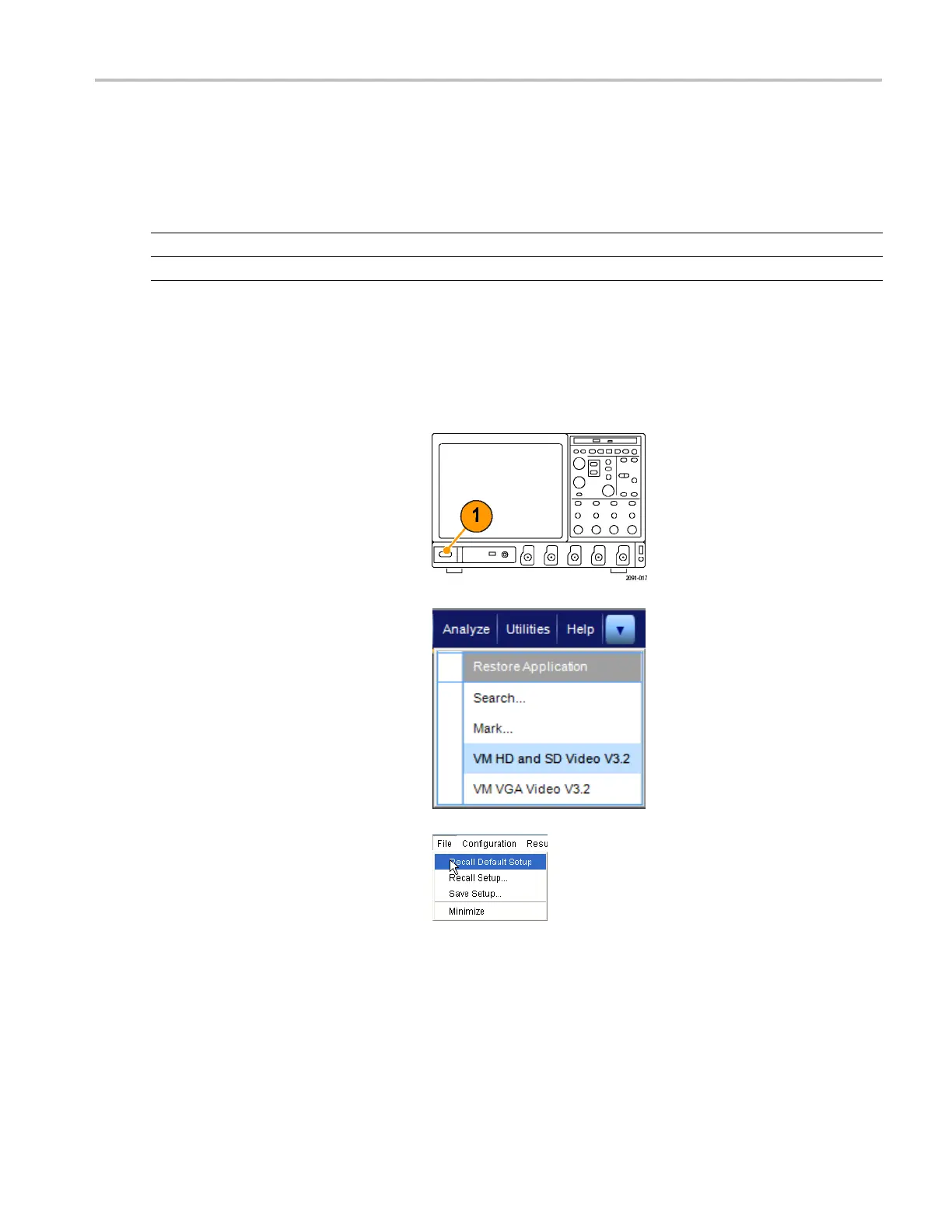
1. Power on the instrument.
2. Select Analyze > VM HD and SD Video
V3.2.
3. In the VM Series s ystem application,
select File > Recall Default Setup to
return all settings to the factory default
values.
4. Connect a signal to the inputs. (See
page 9, Connecting Input Signals.)
5. Set the input signal format. (See
page 32, Setting the Input Signal Format
– Options SD/HD.)
VM Series Video Measurement System Quick Start User Manual 49
 Loading...


