© Telect, Inc., All Rights Reserved, 123518-9 A0
1.509.926.6000 :: telect.com
8
Dual-Feed 200A 4/5 TPA/GMT Fuse Alarm Panel
Power :: 009-8005-0404 :: 009-8005-0404G :: 009-8005-0404L
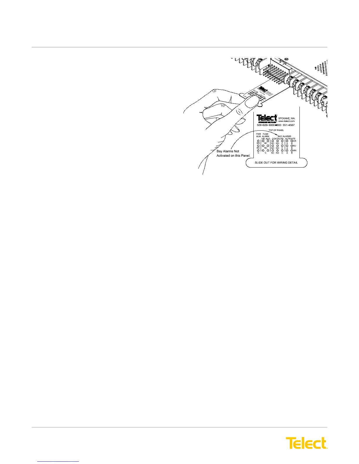
Figure 9 - Alarm Reference Card and Terminals
009-8005-0404
18. At the rear of the panel, pull to extend plastic
reference card below alarm terminals. (See
Figure 9.) With PWR ON A lit (normal
operation)—but with PWR ON B LED off
(failure operation)—test power-fail relay and
contacts at PWR ALM terminals on the rear of
the panel:
• Expect an open circuit (∞Ω) between
Terminals C and NC.
• Expect continuity (0Ω) between
Terminals C and NO.
19. Also, test the fuse alarm relay contacts at the
FUSE ALARM terminals on the rear of the panel.
For both the VIS (visual) and AUD (audible)
indicator contacts,
• Expect continuity (0Ω) between Terminals
C and NC.
• Expect an open circuit (∞Ω) between Terminals
C and NO.
20. Repeat Steps 17 through 20 to power up Side B.
PWR ON A and PWR ON B must both be lit.
2 1. With PWR ON A and B lit (normal operation),
test power-fail relay and contacts at PWR ALM
terminals on the rear of the panel:
• Expect continuity (0Ω) between Terminals
C and NC.
• Expect an open circuit (∞Ω) between Terminals
C and NO.