© Telect, Inc., All Rights Reserved, 123518-9 A0
1.509.926.6000 :: telect.com
9
Dual-Feed 200A 4/5 TPA/GMT Fuse Alarm Panel
Power :: 009-8005-0404 :: 009-8005-0404G :: 009-8005-0404L
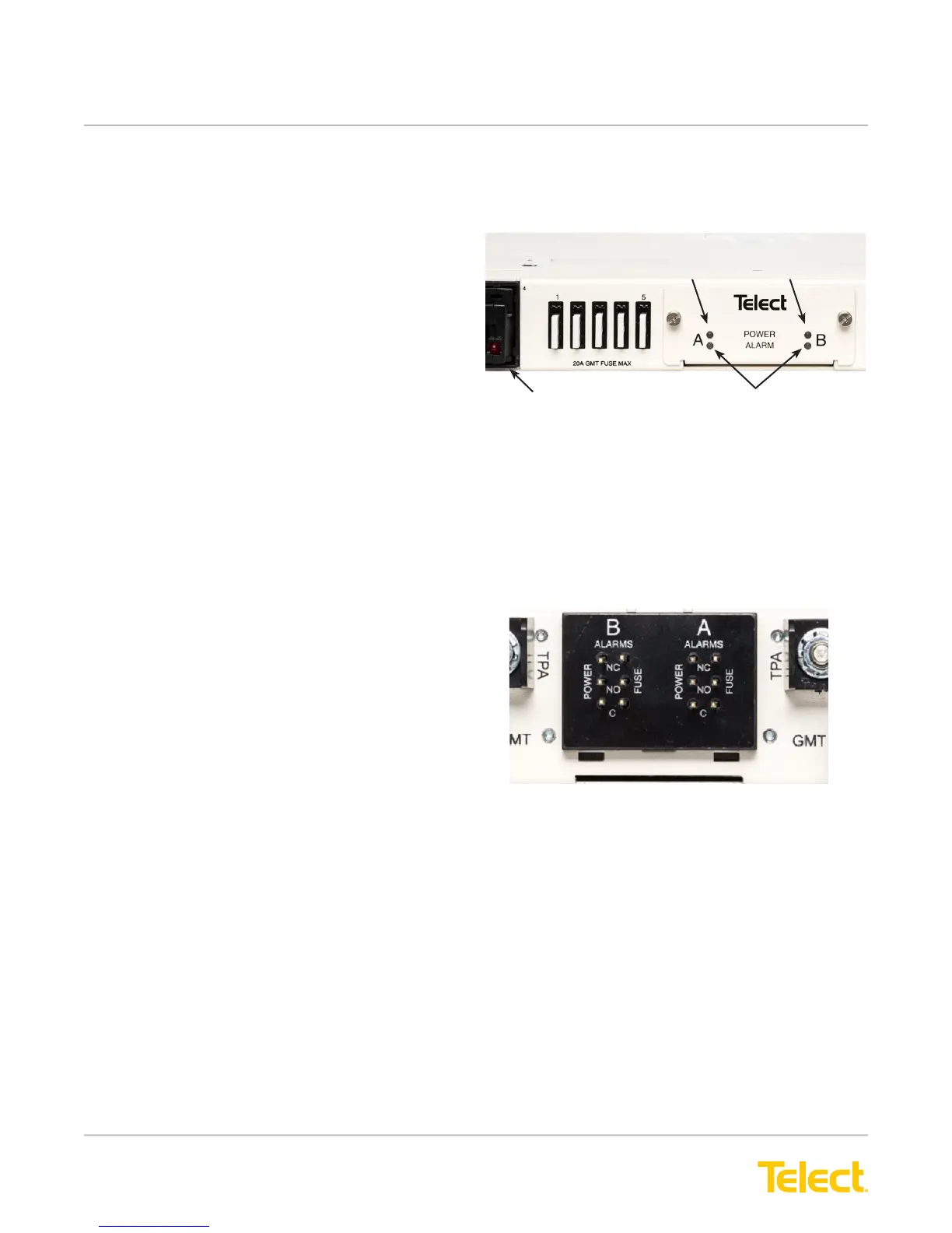
23. With PWR ON A LED lit (normal operation)—
and with PWR ON B LED lit (normal operation)—
test power-fail relay and contacts at PWR ALM
terminals on the rear of the panel:
• expect continuity (0Ω) between Terminals C
and NC.
• expect an open circuit (∞Ω) between Terminals
C and NO.
(See Figure 11 for 009-8005-0404G power alarm
terminals.)
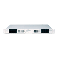
Figure 10 - Alarm Indicators
009-8005-0404G
22. Enable the fuse or breaker at PDU (250A max.)
to turn on Feed A to Side A. Also enable fuse
or breaker at PDU 250A max.) to turn on Feed
B to Side B. Check voltage and polarity at input
connectors of panel. Also, check that,
• POWER ON A LED on front of panel turns on
(green).
• FUSE ALARM LED must be off.
• POWER ON B LED on front of panel turns on
(green).
• FUSE ALARM LED must be off.
(See Figure 10 for 009-8005-0404G alarm indicator
locations.)
For 009-8005-0404 and 009-8005-0404L, continue at
step 24.
Figure 11 - Power Alarm Terminals
009-8005-0404G
For all panels, continue at step 24.
Power A LED Power B LED
Fuse Alarm LED
TPA Fuse
 Loading...