© Telect, Inc., All Rights Reserved, 123518-9 A0
1.509.926.6000 :: telect.com
10
Dual-Feed 200A 4/5 TPA/GMT Fuse Alarm Panel
Power :: 009-8005-0404 :: 009-8005-0404G :: 009-8005-0404L
24. Make sure none of the fuse positions contain
operable fuses.
25. For TPA output wiring, crimp single-hole lugs onto
one end of #18 to #6 AWG copper output wires,
as required by NEC. (Work with one output wire
at a time.)
26. Clean the panel terminals and lugs with a
nonabrasive, nonmetallic pad.
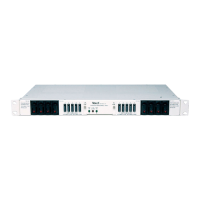
2 7. If required, lightly coat anti-oxidant on lugs and
output BATTERY and RETURN terminals, and
then connect lug to terminals, as shown in
Figure 12. (NEC species only one lug and load
at each output terminal.)
28. Tighten the nuts to 20 in.-lb. (~2.3 N•m).
29. Connect the other end of the output wire to load.
30. For GMT output wiring, use #20 to #12 AWG
copper wire. (Work with one wire at a time.) At
the panel end of the wire, either
• Crimp a single-hole ring or fork lug, as required
by NEC, or
• Strip 3/8 in. (1 cm) of insulation for a bare
wire connection.
3 1. Clean the panel terminals and lug (if applicable)
with a nonabrasive, nonmetallic pad.
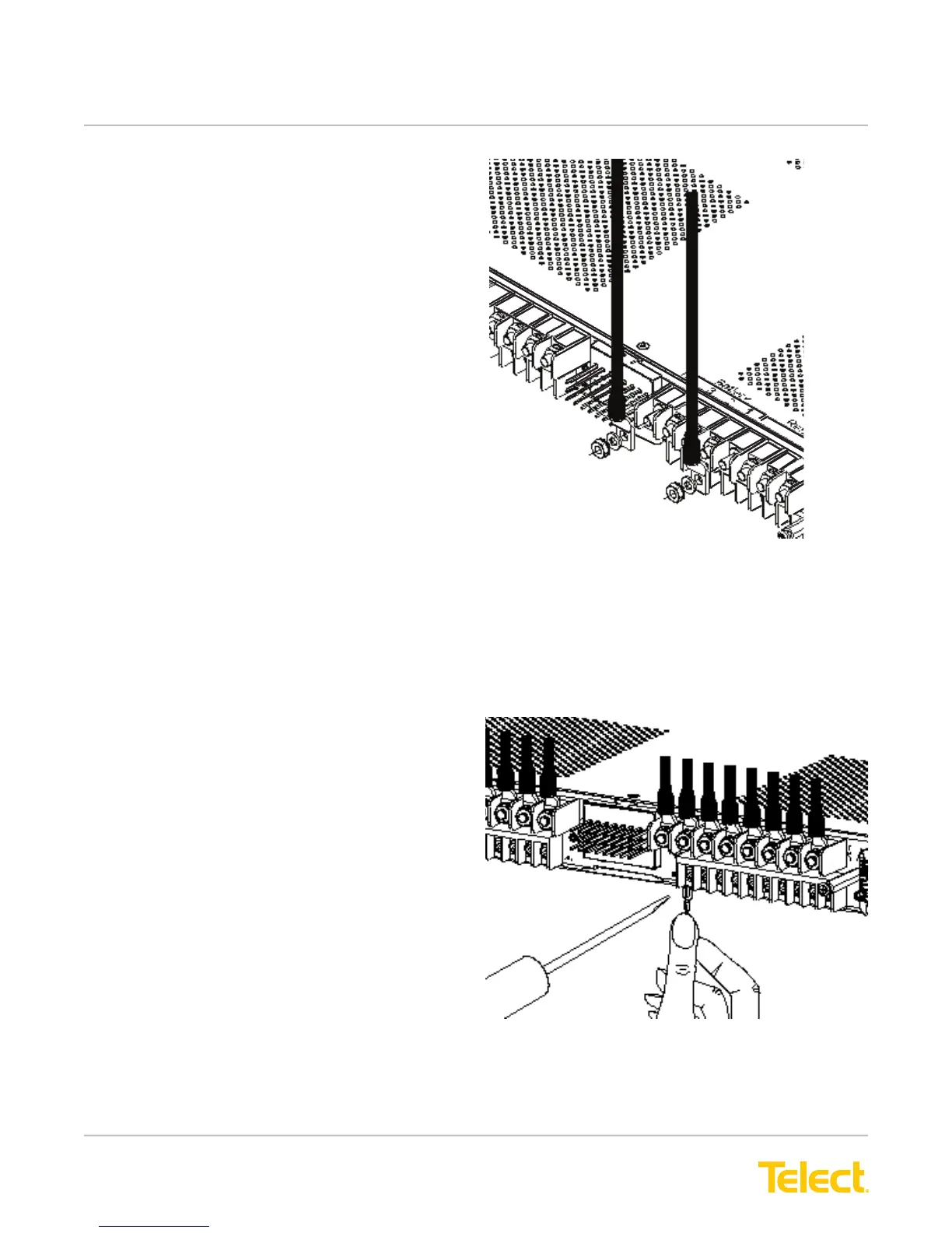
32. If required, lightly coat anti-oxidant on the lug/wire
and output BATTERY and RETURN terminals.
33. Connect to the terminals, as shown in Figure13.
(NEC species only one load at each output
terminal.)
34. Tighten the panhead screws to no more than
8 in.-lb. (~1 N•m).
35. Connect the other end of the output wire to load.
Figure 12 - TPA Output Lug Connections
Figure 13 - GMT Output Lug Connections