© Telect, Inc., All Rights Reserved, 123518-9 A0
1.509.926.6000 :: telect.com
5
Dual-Feed 200A 4/5 TPA/GMT Fuse Alarm Panel
Power :: 009-8005-0404 :: 009-8005-0404G :: 009-8005-0404L
1.3 Installation
Panel brackets provide ush or extended EIA or WECO mounting in a 19 or 23 in. rack. The panel is congured at
the factory for 1 in. extended mounting in a 19 in. rack.
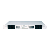
Figure 3 - Bracket Orientation
1. If necessary, remove three screws and
reposition/re-align the brackets on the sides of the
distribution panel, as shown in Figure 3.
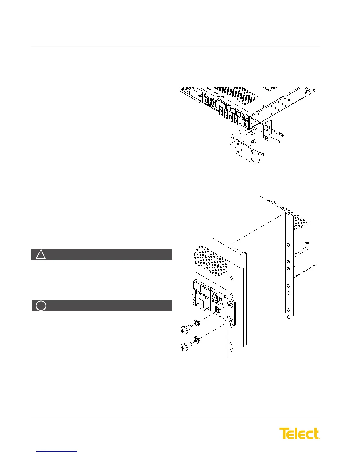
2. Locate an unused rack position and mount the
panel using four screws and lock washers provided,
as shown in Figure 4. (Place the mounting panel as
high as possible on the rack.) Due to the depth and
weight of model 009-8005-0404L, mounting rails
should be used to support the mounted panel in the
rack.
3. Tighten the screws to 35 in.-lb. (4.29 N•m).
4. Loosen (you need not remove) two screws securing
the rear terminal cover on the back of the panel.
5. Remove the cover.
6. Use a listed (approved) crimping tool to attach a
listed (approved), dual-hole compression lug onto a
suitable ground wire. (Size of the ground depends
on input interruption device.)
Figure 4 - Rack Mounting
WARNING! Failure to properly ground this
equipment can create hazardous conditions to
installation personnel and to the equipment.
ALERT! Only use components and crimping tools
approved by agencies or certifying bodies
recognized in your country or region, such as
Underwriter’s Laboratories (UL), TUV, etc.
ALERT