Installation Model 3290
Teledyne Analytical Instruments 18
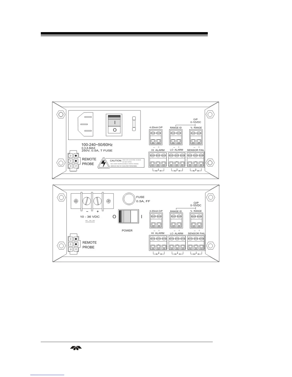
power cord receptacle, accepts a 5 x 20 mm, 0.5 A, time-lag (T) fuse.
(See Fuse Replacement in Chapter 5, Maintenance.)
The power switch is located at the right within the power source
input receptacle assembly.
Figure 3-1: Rear Panel Electrical Connectors for AC & DC Units
Primary Input Power (DC version): The 10–36 VDC power is
connected via the + and terminals in the upper left corner of the panel.
The fuse receptacle, to the right of the power terminal strip, holds a 0.5 A,
very quick acting fuse. (See Fuse Replacement in Chapter 5, Maintenance.)
The Power switch is located below the fuse receptacle.


 To Next Page