Do you have a question about the Teledyne 7320 and is the answer not in the manual?
| Brand | Teledyne |
|---|---|
| Model | 7320 |
| Category | Analytical Instruments |
| Language | English |
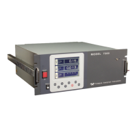
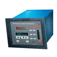
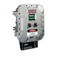
General description of the Teledyne Analytical Instruments Model 7320 Analyzer.
Lists common applications for gas analysis by the Model 7320.
Highlights key functionalities and design aspects of the Model 7320.
Provides a broad overview of the NDIR technology used in the analyzer.
Explains the Non-Dispersive Infrared (NDIR) measurement principle.
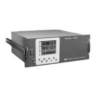
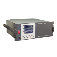
Describes the front panel controls and alphanumeric display of the analyzer.
Details the function of the UP/DOWN control for navigation and selection.
Explains the use of ESCAPE and ENTER for menu navigation and data entry.
Differentiates between Liquid Crystal Display (LCD) and Vacuum Fluorescent Display (VFD).
Summarizes the available electrical connection types for the analyzer.
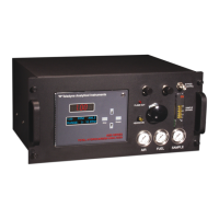
Describes how sample and calibration gases are connected to the analyzer.
Procedure for unpacking the analyzer and inspecting it for damage.
General guidelines for the physical installation of the analyzer unit.
Details on making user-specific electrical and sample connections.
Information and steps for connecting the analyzer to a power source.
Specifies the quality and type of gases required for calibration.
Guidance on making sample and reference gas line connections.
Considerations for designing a reliable sample delivery system.
Safety and operational aspects of venting the analyzer system.
Overview of the various electrical connection points on the analyzer.
Location and type of the primary power input connection.
Instructions for installing or replacing the unit's fuse.
Details on connecting various signals and outputs to terminal blocks.
Description of the analog signal outputs for concentration and range ID.
Configuration and function of the concentration and system failure alarms.
Input terminals for remote control of calibration sequences.
Relays used to indicate the currently active analysis range.
Information on the network communication port and its status.
Connector used for controlling external solenoid valves.
Details on the serial communication port for data output and control.
Specifies gas quality, pressure, and flow rate requirements.
Pre-power-on checks to ensure installation integrity and safety.
General information and recommendations for the calibration process.
Details on the types of zero and span fluids required for calibration.
Step-by-step guide for performing analyzer calibration.
Pre-start-up checks including wiring and connections verification.
Procedures for powering up the analyzer and performing initial checks.
Steps for initial configuration and zero calibration of the analyzer.
Steps for performing calibration during normal analyzer operation.
Explains the fundamental principles behind the NDIR gas analysis.
Basic explanation of how NDIR technology measures gas concentration.
Details on the components and function of the NDIR analyzer.
Describes the internal electronic circuitry of the analyzer.
Explains how signals are processed by the analyzer's electronics.
Describes the process of linearizing the analyzer's output signal.
Details on the optional automatic calibration (zeroing) function.
Overview of operational procedures, configuration, and programming.
How to navigate menus and operate the analyzer using its controls.
Selecting between Analysis and Setup modes for analyzer operation.
The normal operating mode where the analyzer monitors gas concentration.
Mode used for configuring analyzer parameters and settings.
Instructions for entering data and values using the analyzer controls.
Explains the function of the ENTER key for selection and confirmation.
Explains the function of the ESCAPE key for returning to previous screens.
Configuration steps for defining and initiating automatic calibration cycles.
Procedures for establishing and managing password security for settings.
Process for entering the current password to access secured functions.
Detailed steps for setting a new password or modifying an existing one.
How to exit the analyzer in a protected mode without shutting down.
Instructions for running the built-in self-diagnostic routine.
Displaying manufacturer, model, and software version details.
Verifying the accuracy and effectiveness of the linearization process.
How to access specific diagnostic parameters via the HARDW-VAR function.
Adjusting the digital filter to optimize signal response and noise reduction.
Setting a non-zero offset for the zero calibration process.
Procedure for calibrating the analyzer's 4-20mA analog output.
Detailed procedures for performing zero and span calibrations.
Steps and methods for performing a zero calibration.
Procedure for automatic zero calibration.
Procedure for manual zero calibration.
Troubleshooting steps for cell failure indications during zeroing.
Steps and methods for performing a span calibration.
Procedure for automatic span calibration.
Procedure for manual span calibration.
Configuration of concentration alarms, modes, and setpoints.
Manual and automatic selection and definition of analysis ranges.
Selecting and defining specific analysis ranges manually.
Configuration for automatic range switching based on concentration.
Advice on potential pitfalls when setting up ranges for autoranging.
The primary operating screen for monitoring gas concentration.
Advanced configuration of applications, ranges, and algorithms.
Reprogramming analysis ranges, impurity gas, and units.
Setting up linearization curves for accurate signal response.
Verifying the accuracy of the programmed linearization curves.
Procedure for manually inputting linearization data points.
Procedure for automatically determining linearization points.
Configuration of output signal reversal, offset, and polarity.
Adjusting output signals for specific application requirements.
Reversing the polarity of the analog output signals.
Setting an offset value for the analog output signal.
Correcting issues with negative concentration display values.
Setting gain for nonlinear applications to ensure linear readings.
General maintenance tasks including cleaning, fuse replacement, and recalibration.
Instructions for safely removing and replacing the unit's fuse.
Recommended inspection and upkeep schedule for system accuracy.
Inspection and replacement procedures for the system filter element.
Procedures for cleaning the NDIR analyzer's measurement cell.
Instructions for running the built-in system diagnostic test and interpreting results.
Identification of key internal components within the analyzer.
General guidance on diagnosing system and electronic failures.
A table listing common symptoms and their corrective actions.
Technical specifications including ranges, display, outputs, and operating conditions.
Specific gas analysis capabilities and applications for the Model 7320.
List of recommended spare parts for the Model 7320 analyzer.
Information on application exceptions and gas phase conditions.