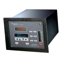
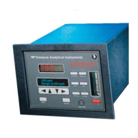
8800 Series Trace Moisture Analyzer Instruction Manual
v
Table of Contents
1.0 Overview of the 8800 Series Trace Moisture Analyzer.......................................................1
2. Sensor and Sampling Techniques ..........................................................................................3
2.1 Precautions using the sensor................................................................................................3
2.2 Sensor Technical Specifications ..........................................................................................4
2.3 Sensor Installation & Sampling Techniques........................................................................4
2.3.1 In-situ Installation.............................................................................................................5
2.3.2 Extractive Installation .......................................................................................................6
2.4 Mechanical Installation........................................................................................................7
2.5 Troubleshooting unexpected readings .................................................................................8
3. Instrument ..............................................................................................................................9
3.1 Precautions using the 8800 Series Trace Moisture Analyzer ..............................................9
3.1.1 Electromagnetic Compatibility Considerations................................................................9
3.2 Instrument Technical Specifications..................................................................................10
3.3 Installation .........................................................................................................................11
3.3.1 Instrument Mechanical Installation ................................................................................11
3.3.1.1 8800A (DIN43700) Enclosure Installation..................................................................11
3.3.1.2 8800B (IP65) Enclosure Installation............................................................................11
3.3.2 Electrical Connections ....................................................................................................12
3.3.2.1 Connecting Power........................................................................................................12
3.3.2.1.1 AC Mains Electrical Power Connection...................................................................13
3.3.2.1.2 Low Voltage DC Powered Option - Electrical Power Connection...........................13
3.3.2.2 Sensor Connection .......................................................................................................13
3.3.2.3 Wiring the Alarm Contacts ..........................................................................................13
3.3.2.4 Interfacing to the Analog Output .................................................................................14
3.3.2.5 Interfacing to the RS-232 option .................................................................................15
3.4 Operating the Instrument ...................................................................................................15
3.4.1 Starting up.......................................................................................................................15
3.4.2 Display Conventions.......................................................................................................16
3.4.3 Push Buttons ...................................................................................................................16
3.4.4 Operating State ...............................................................................................................17
3.4.4.1 Viewing Dewpoint Mode.............................................................................................17
3.4.4.2 Alarms..........................................................................................................................19
3.4.4.3 Start Calibration...........................................................................................................20
3.4.4.3.1 SpanCheck™ Mode..................................................................................................20
3.4.4.3.2 Single Point Self Calibration, manual or scheduled .................................................22
3.4.4.4 Viewing Serial Number Mode.....................................................................................25
3.4.5 SetUp State .....................................................................................................................25
3.5 Resetable Audio-Visual Alarm Option (NFPA compliant)...............................................28
3.6 Troubleshooting the Instrument.........................................................................................29
3.7 Maintenance.......................................................................................................................31
Glossary ...................................................................................................................................33
Appendix A: Flow Diagram of Operating State User Interface ..............................................37
Appendix B: Flow Diagram of Set-Up State User Interface ...................................................39
Appendix C: Sensor Mechanical .............................................................................................40