operation.
2.6.1
Using new
inset
½” metal seal
Hand-tighte
damaged
possibili
2.6.2
connect inlet
2.6.3
pressurised
Fig
peratures are generated during normal operation.
-
work as this can get hot during n
Risk. Very low temperatures generated during
. Avoid contact with exposed pipe
-work.
ilver plated “O” seal (supplied in ac
refrigerant line co
fitting. The “Coil In” (CI) is a ½” metal seal
coil) and the “Coil Out”
female fitting (f
rom the Meissner coil to the unit)
n the nuts to ensure that the
the installation process.
ings are fully tightened. Installation engineers mu
-
90nn) on the couplings to minimiz
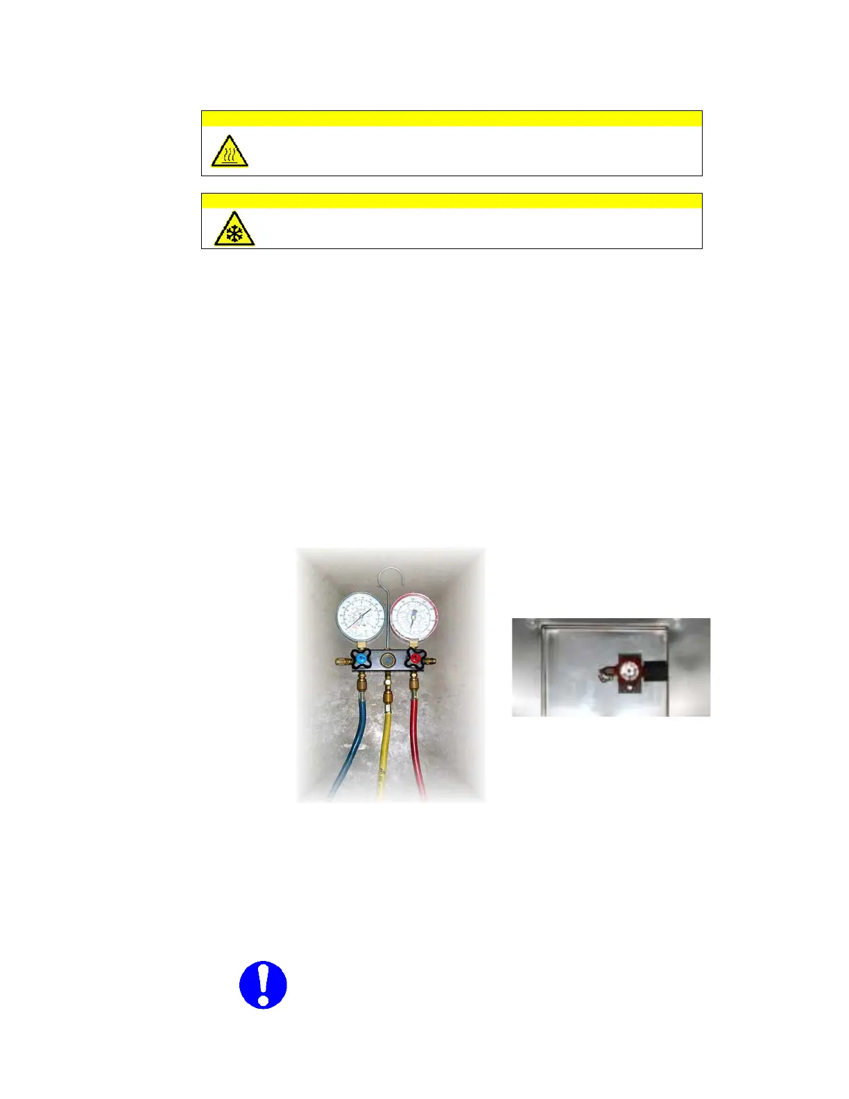
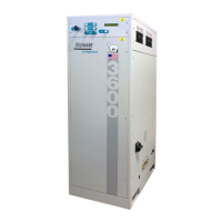
of Refrigerant Manifold gauges as shown below (
(centre (yellow hose) to a
high pressure
valve (see fig 7).
see fig 7)
3.78Bar (1.78Mpa)). Using a su
apy water) check the connectio
hiller ends for signs of leakage. T
at leas
t 15 minutes while inspection is checke
Note:
When pressurising the lines,
DO NOT
the balance pressure of the unit.
Refrigerant Manifold
fig 8)
manifold
exceed