iRIS8 - Addressable Fire Alarm Panel – Installation Manual
10
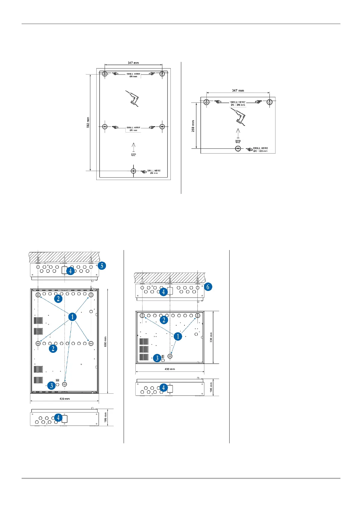
2.2. Wall Mounting
• For wall mounting, use the drilling paper template to mark the mounting holes – Figure 4.
• For mounting of iRIS8 B, drill holes Ø8mm and for mounting of iRIS8 S – Ø6 ÷ Ø8mm.
Figure 4
• Fix the box bottom with the supplied anchors and mounting screws.
• The elements of the metal box bottom are described on Figure 5.
1 - Main mounting holes
2 - Holes for cable running
3 - Hole for main power supply cable
running, protected with a metal cap
element
4 - Additional holes for cable
running, protected with a metal cap
element
5 (iRIS8 B) - Ø6mm openings
protected with plastic caps (6 on
upside and 6 on downside on the
box bottom) for building of modular
structure with IRIS PS72 (external
power supply) and IRIS termal
printer
6 (iRIS8 S) - Ø6mm openings
protected with plastic caps (6 on
upside and 6 on downside on the
box bottom) for building of modular
structure with iRIS8 Ext (4 loop
expander box), IRIS PS72 (external
power supply) and IRIS termal
printer