iRIS8 - Addressable Fire Alarm Panel – Installation Manual
16
4. BASIC MODULES DESCRIPTION
The iRIS8 is delivered with plug connectors (2- and 3-position) mounted to the PCB control modules of
OUT1, OUT2, Loop expander(s) and interface communication module – see Figure 14. The plug
connectors are used for quick wire installation.
To unplug a connector, just pull it up from the terminal. To plug it back, press down until a click is heard.
Attention:
The basic modules are factory wired with interface and grounding cables, depending on panel configuration.
DO NOT unplug, modify or change the factory connection cables to avoid malfunctioning of the panel!
Follow the instructions for electrical safety and operation during the installation!
Adding of any addition modules MUST be done only with main and back-up supplies off!
4.1. Main Power Supply and Back-up Battery Connection
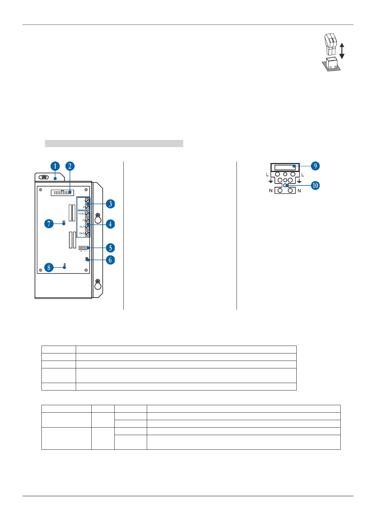
4.1.1 Main Power Supply Elements Description
1 - Metal cover of the main power
supply unit.
2 - Inrerface connector for
communication with control output
module (factory mounted).
3 - Power supply for control output
module (factory mounted).
4 - Terminal Block for connecting to
external power supply – see the
description below.
5 - Wires for connection the back-up
battery (factory mounted).
6 - Temperature sensor (factory
mounted).
7 - Red LED for indication of
110÷230V AC power source
presence.
8 - Green LED for indication the status
of communication with the control
output module.
Fuse terminal block for connection to
110÷230V AC power source.
9 – Fuse 4A.
10 – Terminal body, wire-to-wire
connection.
Figure 15
Terminal Block for connecting to external power supply:
External power supply input.
Input for connecting the Fault output of the external power supply.
Fault output, turns on when a problem with the main power supply occurred.
Connect it to the input (Fault In) of the external power supply.
Input for connecting of external power supply EARTH.
LED Indication of Main power supply unit:
Power supply with 110÷230V AC power source.
The 110÷230V AC power source is switched off or missing.
Communication with the control output module (OUT1 or OUT2).
No communication with the control output module (OUT1 or OUT2).
Fault or switched off interface cable (Figure 15, position 2).