iRIS8 - Addressable Fire Alarm Panel – Installation Manual
14
3. SYSTEM COMPONENTS
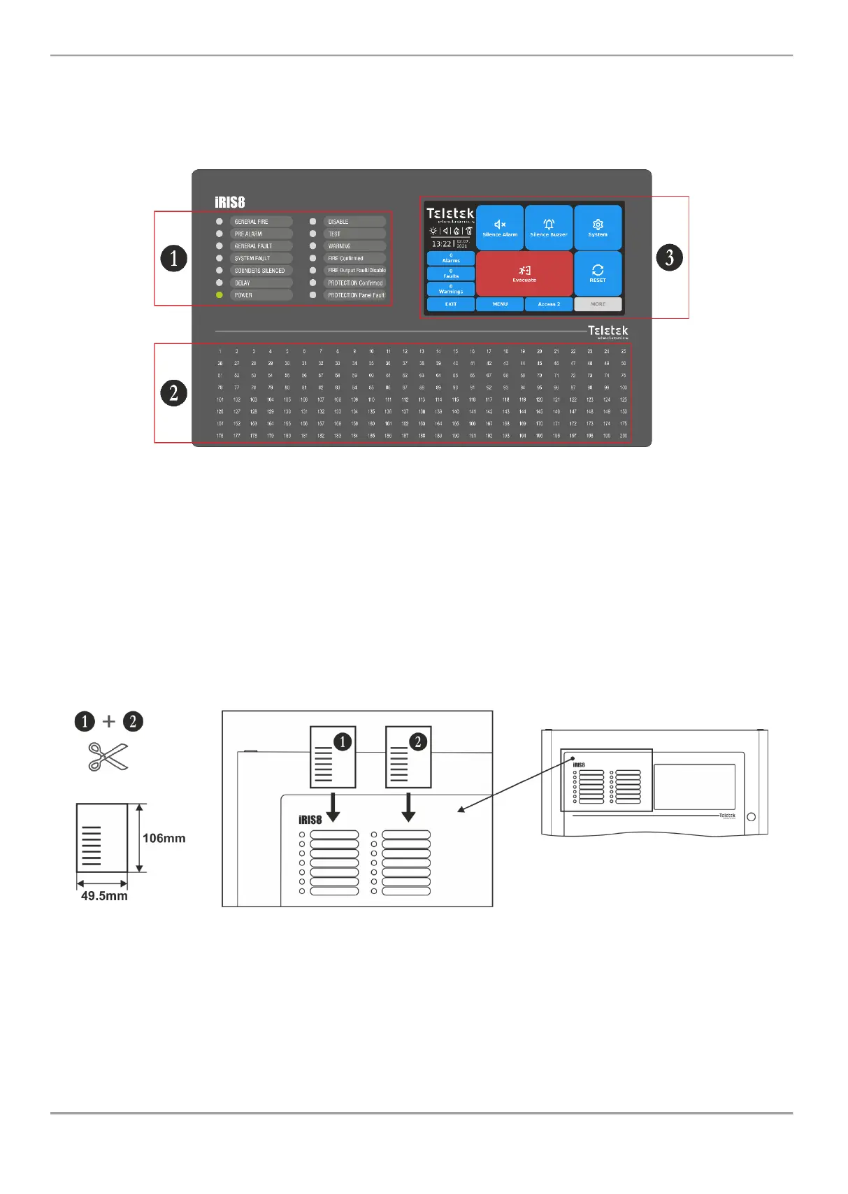
3.1. Front Panel
The front panel of iRIS8 presents detailed information of the current system status (1) and activated zones (2) via LED
indication. The operation, control and programming of the panel is via the TFT screen (3) – Figure 12.
Figure 12
3.2. LED Indication for the System Status
The LED indication supports Users in operation with iRIS8 and presents a quick review of the system status without
reviewing the programming menus.
The system status descriptions are printed on two separate paper labels and can be replaced if needed, including for
language change. The paper labels (numbered 1 and 2) are placed in two special openings on the back side of the front
door, over the Main control module PCB – see Figure 14.
Note: The front door of iRIS8 addressable fire panel is secured with special key-lock (1 pc in iRIS8 S; 2 pcs in iRIS8 B)
for limited access only from technical support specialist.
Figure 13
The system status is displayed also with color LEDs. In case of fire alarm, common or system faults, settings for delays
or disablements, tests or warnings, the LED is lighting on permanently. In case of fault in Fire Output on the main
control PCB the respective LED is blinking.
Note: The detailed description of LED indication for system status is available in “iRIS8 Engineer Programming Manual”.