iRIS8 - Addressable Fire Alarm Panel – Installation Manual
21
4.5.1 Permissible Cable Length
The maximum length of the loop in the system could vary according to the cross-section and the ohmic resistance of the
used cable.
Nevertheless, there is no specific requirement for cable description according to standard EN 54-2, the manufacturer
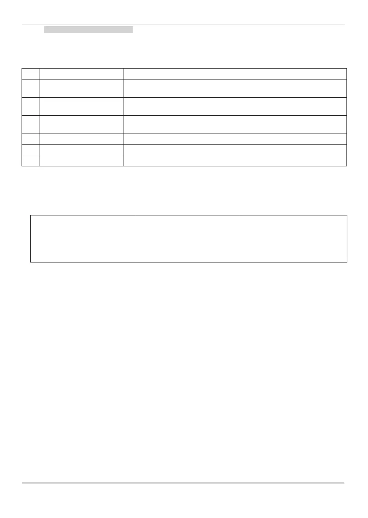
recommends using the listed cables in installations:
Mining Ltd Fire cable AF*
Unscreened, CEI 20/22 II IEC 60332-3, GR2, C-4 (U0=400V) CEI-UNEL-36762,
2x0.8mm
2
BERICA CAVI S.P.A ITALY
MULTICORE FLEX SCR
Screened, CEI 20/22 II CEI EN 60332-1-2, CL 5 CEI EN 60228 VDE 0295,
300/500V, 2x0.5/0.75/1.0/1.5mm
2
TEKAB FireTEK, SA7Z1,
ZA7Z1, MZA7Z1
Screened, C/W BS 6387, Class-1/Class-2 BS 6360, 300/500V, 2x1.0/1.5/2.5mm
2
Screened, IEC332,2, 2x1.0/1.5/2.5mm
2
Screened, IEC332,2, 2x0.8mm
2
Screened, PH90 DIN EN 50200 TS IEC 60331-2, 300/500V, 2x0.8/1.5mm
2
*This cable is tested and approved.
ATTENTION: iRIS8 TTE loop controller supports up to 250 devices!
To ensure the correct operation of the system is necessary to make some calculations in advance:
1. To ensure the ability of the fire
panel to receive the signals from the
devices in the loop, calculate:
L
C1max
≤ 123 / R
C
2. To ensure the ability of the fire
panel to recognize the double
addresses in the system, calculate:
L
C2max
≤ 62 / R
C
3. To ensure the ability of the devices
in the loop to receive command
signals from the panel, calculate:
L
C3max
≤ (12 / I
max
- R
i
) / R
C
Where:
L
C1MAX
, L
C2MAX
and L
C3MAX
- are maximum permissible length of the used cable, [km];
R
C
- is total ohmic resistance of the two wires of the used able; its value shows the magnitude of the cable resistance at
length 1km [Ω/km];
R
I
- is the total resistance of the isolator modules in the loop;
I
max
- is the maximum current consumption in the loop in alarm condition - total amount of the current consumption of all
devices in alarm state** in the loop.
Note: In case of using more than 15 devices SensoIRIS series from type T110/ T110 IS, S130/ S130IS, M140/ M140IS,
MCP150 and MC-Z, in calculation of I
max
value is used the maximum current consumption in alarm state** only for those
15 devices with the highest consumption, and for the rest devices is used the consumption in stand-by mode**.
** For the max. current consumption in alarm state and the consumption in quiescent state with communication (stand-by mode) of a device refer to its
installation manual.
L
C
- is the necessary length of the cable for the loop.
After calculating, the maximal length of the cable is determined according:
·
If L
C
≤ L
C2max
and L
C
≤ L
C3max
- the fire panel will be able to communicate with the devices in the loop and also will
be able to identify the presence of double address.
·
If L
C2max
< L
C
≤ L
C1max
and L
C
≤ L
C3max
- the fire panel will be able to communicate with the devices in the loop but
will not be able to identify the presence of double addresses.
ATTENTION: Always calculate the maximal cable length according the mentioned above formulas!
IF L
C
> L
C1max
or L
C
> L
C3max
- the fire panel would not be able to communicate with the devices.