iRIS8 - Addressable Fire Alarm Panel – Installation Manual
30
5. SUPPLEMENTARY INFORMATION
5.1. Periphery Devices
All “functional modules” connected to the control panel configuration are defined as Periphery Devices, and have
special programming and settings.
Attention: The Interface module and Main control module PCB are not periphery devices!
Up to 12 periphery devices can be added to the system configuration of iRIS8 panel. The number and type of the
functional modules depend on the panel’s model.
Model and max. number of supported periphery devices
System name and description
LOOP – Loop controller (expander)
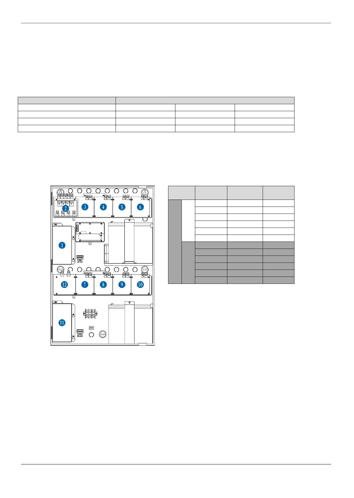
The periphery devices have factory set address numbers that cannot be changed. The following diagram shows the
position and the set factory addresses. The loop controllers always take addresses from 3 to 10.
The following drawing of the hardware configuration of iRIS8 panel models and table represent the fixed factory
addresses of the periphery devices, which must be assumed during the initial power up and programming of the whole
system.
The free addresses for periphery devices are
presented as EMPTY.