iRIS8 - Addressable Fire Alarm Panel – Installation Manual
22
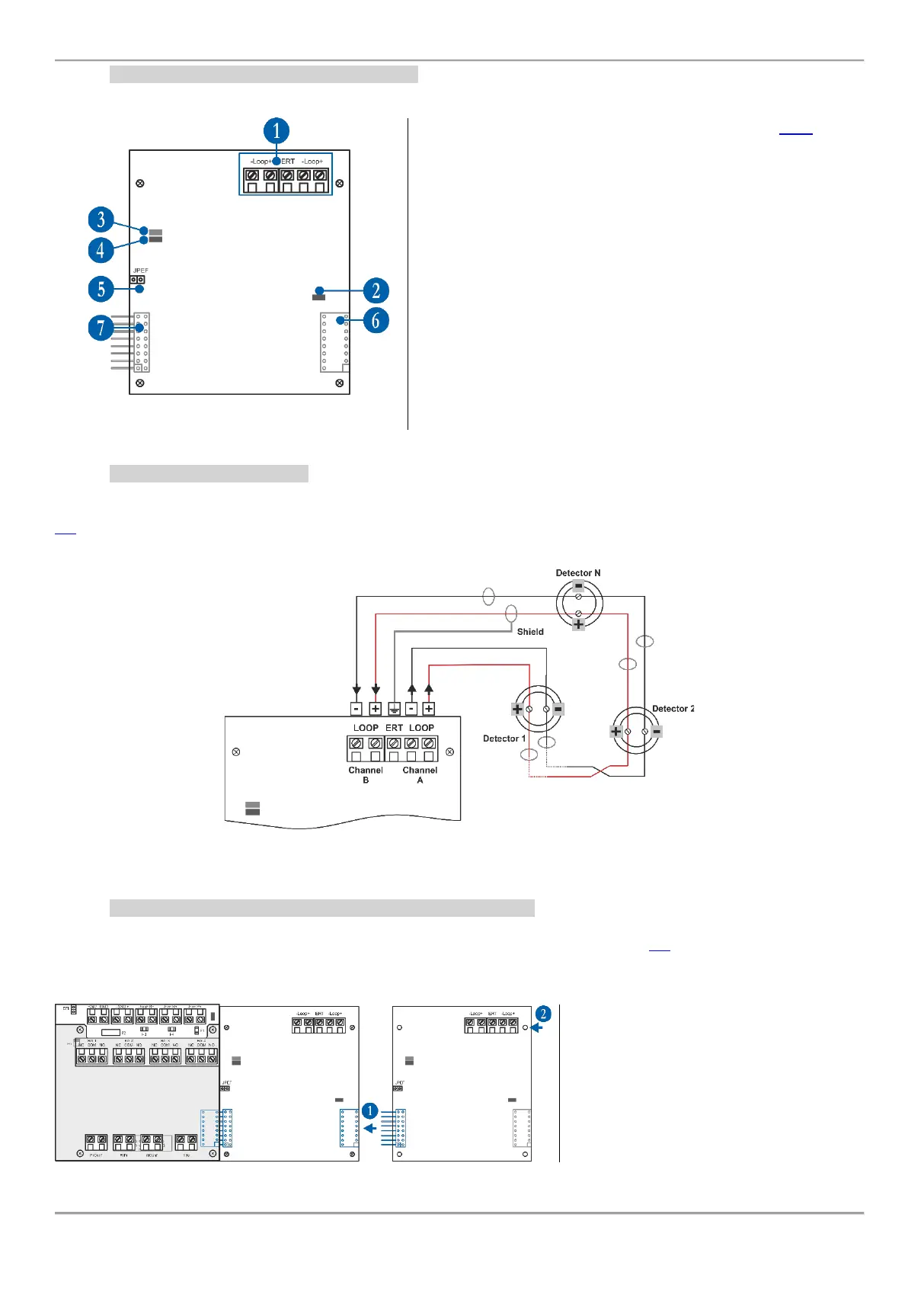
4.5.2 Loop Expander Elements Description
1 - Interface for connection of the loop line – see item 4.5.3.
2 - LED (red) – Indication for power supply of the Loop
expander. In normal operation mode it is constantly lighting on.
3 - LED (green) – Indication for data transfer between the main
microprocessor of the panel and the Loop expander. In normal
operation mode it is constantly blinking.
4 - LED (red) – Indication for scanning the devices connected
to the Loop expander. In normal operation mode the LED
lights on continuously in 10 seconds intervals.
5 - Jumper for enable/disable indication for earth fault (JPEF).
For example, if you want to enable the earth fault indication set
a jumper.
6 - Interface connector for connecting the next Loop expander
(on the back side of the Loop expander).
7 - Interface connector for connecting the Loop expander to
the Output Module or to other (previous in order) loop
expander (on the back side of the Loop expander).
4.5.3 Loop Line Connection
Connect the loop line to the iRIS8 Loop expander as strictly observe the polarity. The “Channel A” is the starting point
for addressing the connected devices, and “Channel B” is the end point. The addressing methods are described in item
5.2. To avoid faults and malfunctioning of the system, the loop line must be connected to the Loop expander only
when the main and back-up supplies of the panel are off!
Figure 23
4.5.4 Adding Loop Expanders and Possible Configurations
The loop expanders are periphery devices in iRIS8 system configuration. According the physical place of mounting,
every loop expander takes a system factory address that cannot be changed – see item 5.1 for general information
about the periphery devices addressing.
The connection between the loop expanders is via interface connectors for coupling the modules to each other.
1 - Connect the interface connectors of the
first and the second loop expanders.
2 - Fix the second loop expander to the
metal carrier of the panel.
The Loop expanders must be added or
removed from the system configuration
only when the main and back-up power
supplies are off!
iRIS8 OUT1
Control Module
(Address 2)
Loop 1
Expander
(Address 3)
Loop 2
Expander
(Address 4)