iRIS8 - Addressable Fire Alarm Panel – Installation Manual
8
List of the fuses
• General Power Supply, T Type: ......................................... 4A
• Outputs, PTC Type:
o Fire Protection, Fire, Fault..................................... 3x0.1A
o Auxiliary ................................................................. 1x0.3A
o Auxiliary ................................................................. 1x0.5A
o Sounder ................................................................. 2x1A
• Battery, PTC Type: ............................................................. 4x15A
ATTENTION: Do not install the fire panel near power electromagnetic fields (radio equipment,
electric motors, etc.)!
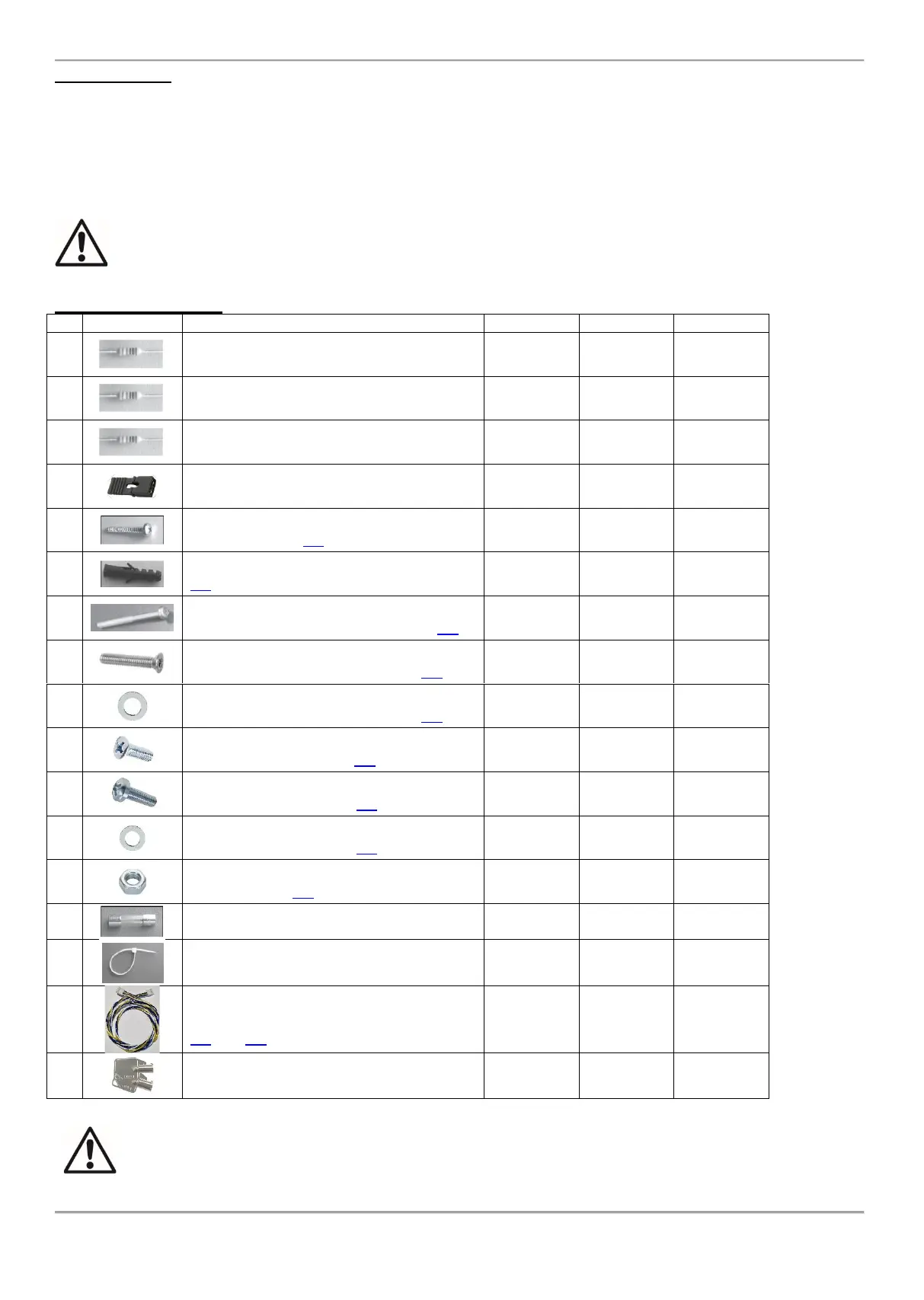
List of spare parts kits:
Screw 4.2х38, cross slot, DIN7981 (wall
mounting – item 2.2)
Anchor 6х30mm (wall mounting – item
2.2)
Screw M4x40, cross slot, DIN7985 (built-
in mounting in 25 mm drywall – item 2.3)
Screw M4x30, cross slot, DIN 965 (built-in
mounting in 25 mm drywall – item 2.3)
Washer M4 DIN 522, ø12mm (built-in
mounting in 25 mm drywall – item 2.3)
Screw M4x12 DIN 966 (built-in mounting
in 25 mm drywall – item 2.3)
Screw M5x10 DIN 7985 A2 (for modular
structure building – item 2.4)
Washer ø5,3 DIN 125 (for modular
structure building – item 2.4)
Nut M5 DIN934 (for modular structure
building – item 2.4)
Fuse 4А, glass time-delay type 5x20mm
(for the main power supply terminal)
Serial connection cable, ~800mm
(between iRIS8 S and iRIS8 Ext – items
4.4 and 4.8)
ATTENTION!
Qualified specialists only should install the panel.
The electronic components of the panel are vulnerable to electrostatic discharge.
Never add or turn off components which are being power supplied!