LE910Cx Hardware Design Guide
1VV0301298 Rev.40 Page 42 of 149 2023-03-16
Not Subject to NDA
5. HARDWARE COMMANDS
Turning on the LE910Cx Module
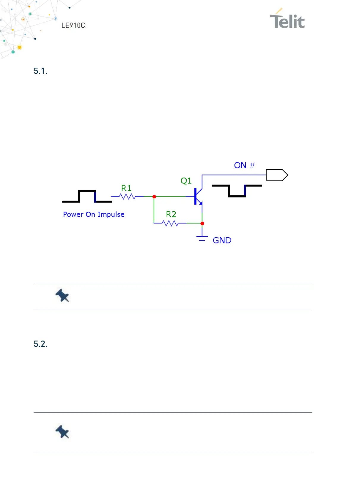
To turn on the LE910Cx module, the ON_OFF_N pad must be asserted low for at least 1
second and then released.
The maximum current that can be drained from the ON/OFF # pad is 0.1 mA. This pin is
pulled up internally; customers should expect to see ~ 800 mV on the output.
Figure 4 illustrates a simple circuit to power on the module using an inverted buffer
output.
Figure 4: Power-on Circuit
Note: Recommended values R2 = 47 kΩ, R1 = 10 kΩ.
Initialization and Activation State
After turning on the LE910Cx module, a predefined internal boot sequence performs the
HW and SW initialization of the module, which takes some time to complete. During this
process, the LE910Cx is not accessible.
As shown in Figure 5, the LE910Cx becomes operational at least 20 seconds after the
assertion of ON_OFF.
Note: During the Initialization state, the AT commands are not
available. The DTE host must wait for the Activation state before
communicating with the LE910Cx

 Loading...


