LE910Cx Hardware User Guide
1VV0301298 Rev. 1.05 - 2017-06-18
Reproduction forbidden without written authorization by Telit Communications S.p.A. - All Rights Reserved
Telit Confidential Information, provided under NDA Page
104 of 117
11.3. SIM Interface
This section presents the recommended schematics for the design of SIM interfaces on the
application boards. The LE910Cx supports two external SIM interfaces.
11.3.1. SIM Schematic Example
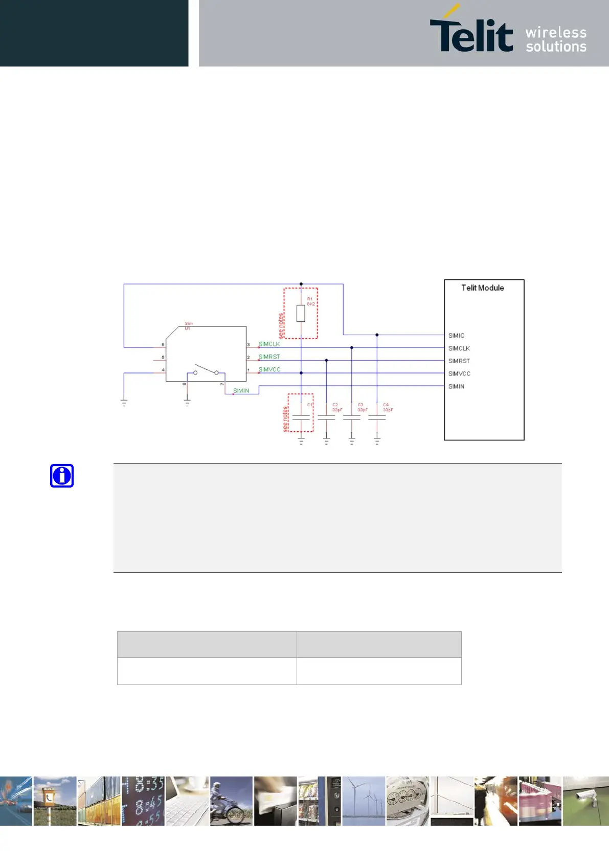
Figure 28 illustrates in particular how the application side should be designed, and what values the
components should have.
Figure 28: SIM Schematics
NOTE:
The resistor value on SIMIO pulled up to SIMVCC must be defined to be compliant with the 3GPP
specification for USIM electrical testing.
The LE910Cx module contains an internal pull-up resistor of 20K Ω on SIMIO.
However, the un-mounted option in the application design can be recommended to tune R1 if
necessary.
Table 40 lists the values of C1 to be adopted with the LE910Cx product:
Table 40: SIM Interface – C1 Range
Product P/N C1 Range (nF)
LE910Cx 100 nF
Refer to the following document for details:
• Error! Reference source not found.