LE910Cx Hardware User Guide
1VV0301298 Rev. 1.05 - 2017-06-18
Reproduction forbidden without written authorization by Telit Communications S.p.A. - All Rights Reserved
Telit Confidential Information, provided under NDA Page
49 of 117
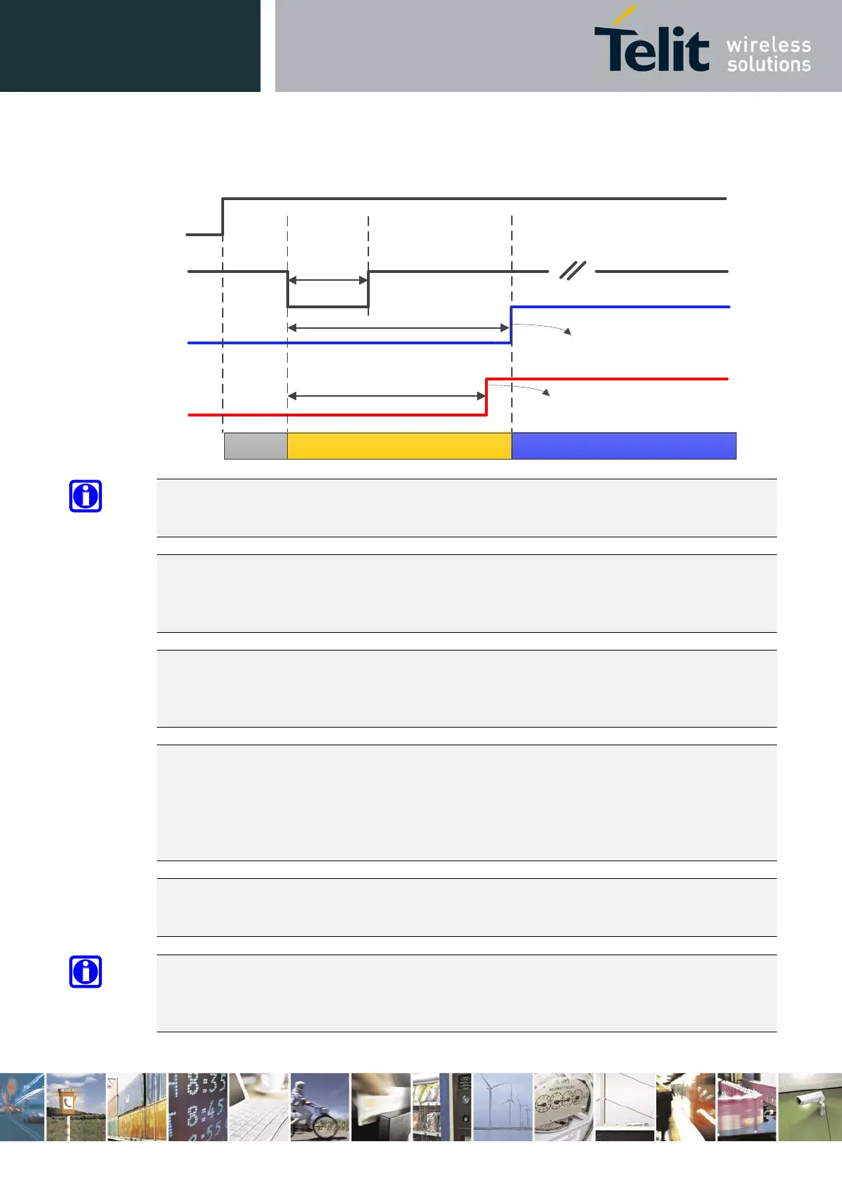
Figure 5: LE910Cx Initialization and Activation
NOTE:
SW_RDY signal is available on GPIO_08 (by default GPIO_08 functions as SW_RDY)
NOTE:
To check if the LE910Cx has completely powered on, monitor the SW_RDY signal. When SW_RDY
goes high, the module has completely powered on and is ready to accept AT commands.
NOTE:
During SW initialization of the LE910Cx, the SW configures all pads and interfaces to their desired
mode. When PWRMON goes high, this indicates that the initialization of all I/O pads is completed.
NOTE:
Do not use any pull-up resistor on the ON/OFF# line as it is internally pulled up. Using a pull-up
resistor may cause latch-up problems on the LE910Cx power regulator and improper powering
on/off of the module. The ON/OFF# line must be connected only in an open-collector
configuration.
NOTE:
Active low signals are labeled with a name that ends with "#" or with “_N”
NOTE:
To avoid a back-
powering effect, it is recommended to avoid having any HIGH logic level signal
applied to the digital pins of the module when it is powered OFF or during an ON/OFF transition.
1 Sec < T_Hold < 2 Sec
VBATT
ON_OFF
SW_RDY
T_RDY < 20 Sec
V_AUX
PWRMON
18 Sec < T_PWRMON < 20 Sec
OFF State
Initialization State
Active State
OK to Send AT
commands
All interfaces and pins
configured