LE910Cx Hardware User Guide
1VV0301298 Rev. 1.05 - 2017-06-18
Reproduction forbidden without written authorization by Telit Communications S.p.A. - All Rights Reserved
Telit Confidential Information, provided under NDA Page
94 of 117
10. Mounting the Module on your Board
10.1. General
The LE910Cx module was designed to be compliant with a standard lead-free SMT process.
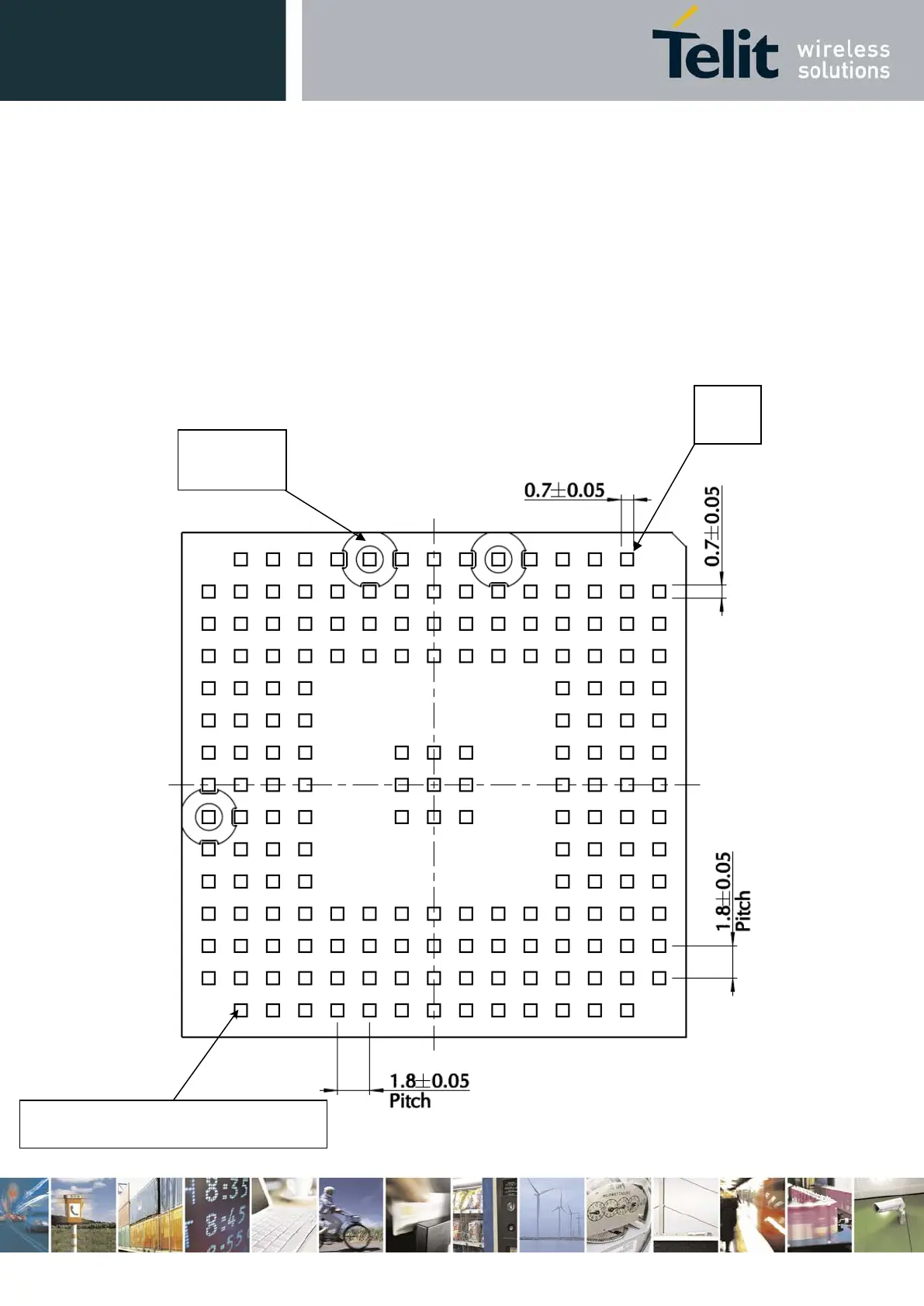
10.2. Finishing & Dimensions
Figure 21 shows the mechanical dimensions of the LE910Cx module.
Figure 21: LE910Cx Mechanical Dimensions (bottom view)
Surface finishing Ni/Au for all solder pads
Inhibit
B1