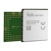
ME910C1 HW User Guide
1VV0301351 Rev.8 Page 56 of 99 2018-09-28
The following table shows the available GPIO on the ME910C1:
PAD Signal I/O Output
Drive
Strength
Default State NOTE
C8 GPIO_01 I/O 1mA
INPUT – PD (100K)
Alternate function
STAT LED
C9 GPIO_02 I/O 1mA
INPUT – PD (100K)
C10 GPIO_03 I/O 1mA
INPUT – PD (100K)
C11 GPIO_04 I/O 1mA
INPUT – PD (100K)
B14 GPIO_05 I/O 1mA
INPUT – PD (100K)
C12 GPIO_06 I/O 1mA
INPUT – PD (100K)
C13 GPIO_07 I/O 1mA
INPUT – PD (20K to 100K)
(*)
K15 GPIO_08 I/O 1mA
INPUT – PD (100K)
L15 GPIO_09 I/O 1mA
INPUT – PD (18K)
G15 GPIO_10 I/O 1mA
INPUT – PD (100K)
(*) If used, GPIO_07 must not be pullup to 1.8V during ME910 poweron.
5.8.1. Using a GPIO as INPUT
The GPIO pads, when used as inputs, can be connected to a digital output of another
device and report its status, provided this device has interface levels compatible with the
1.8V CMOS levels of the GPIO.
Input current (@1.8V) is about 18uA (corrisponding to 100K pulldown value) in all GPIO
pin expect GPIO_09 where current is about 100uA. This value is present since ME910
poweron.

 Loading...