- 8 -
- Tighten the spool lock nut, using spacers as and where necessary (1a).
- Free the pressure counter-roller/s and distance it/them from the lower roller/s (2a);
- Make sure the pulling feeder/s is/are suitable for the wire being used (2b).
- Free the wire end, cut off the misshaped end by cutting it cleanly and without leaving
a burr; rotate the spool counter-clockwise and position the wire end into the wire feed
input, pushing it by 50-100 mm into the torch connecting wire feed (2c).
- Reposition the counter-roller/s, adjusting the pressure at an intermediate value,
make sure the wire is positioned correctly in the hollow of the lower feeder/s (3).
- Remove the nozzle and contact tube (4a).
- Insert the welding machine plug into the mains socket, switch on the welding
machine, press the torch push-button or the wire forward push-button (Fig. C-2) and
wait for the end of the wire which is running along the whole wire feed casing, to exit
by 10-15 cm from the front of the torch, then release the push-button.
ATTENTION!Duringtheseoperationsthewireisbeingpoweredand
issubjecttomechanicalforce;ifsuitableprecautionsarenottakenthereisa
dangerofelectricshockandwounds,andelectricarcsstriking:
- Do not direct the torch mouth against parts of the body.
- Do not approach the torch gas cylinder.
- Remount the contact tube and the nozzle onto the torch (4b).
- Make sure the wire exits regularly; set the roller pressure and reel braking (1b) to the
lowest values possible, making sure the wire does not slide in the hollow and that
when the drive stops the wire turns do not become loose because of too much spool
inertia.
- Cut the end of the wire that exits from the nozzle by 10-15 mm.
- Close the reel area door.
5.5REPLACINGTHETORCHWIREGUIDESHEATH(FIG.H)
Before replacing the sheath, straighten out the torch cable to make sure there are no
loops.
5.5.1Spiralsheathforsteelwire
1- Remove the nozzle and contact tube from the torch head.
2- Unscrew the sheath lock nut on the central connector and slide out the existing
sheath.
3- Slide the new sheath into the torch cable and gently push it until it comes out of the
torch head.
4- Hand tighten the sheath lock nut back in place.
5- Cut the wire ush with the sheath and gently squeeze them together; remove it
from the torch cable.
6- Bevel the sheath cutting zone and reposition it in the torch-cable duct.
7- Use a key to tighten the lock nut back in place.
8- Remount the contact tube and the nozzle.
5.5.2Syntheticsheathforaluminiumwire
Perform operations 1, 2 and 3 foreseen for steel sheaths (do not consider operations
4, 5, 6, 7 and 8).
9- Screw the aluminium contact tube back in place checking that it comes into contact
with the sheath.
10- Insert the brass nipple, the OR ring onto the opposite end of the sheath (torch
coupling side), maintain a light pressure on the sheath and tighten the sheath lock
nut. The excess section of the sheath shall be removed later on (see (13)). Slide
out the capillary tube for steel sheaths from the wire feeder torch coupling.
11- NO CAPILLARY TUBE IS FORESEEN for aluminium sheaths with diameters of
1.6-2.4 mm (yellow colour); the sheath will be inserted in the torch coupling without
it.
Cut the capillary tube for aluminium sheaths measuring 1-1.2 mm (red colour) to
a length of 2 mm less than the one used for the steel tube and insert it on the free
end of the sheath.
12- Insert and block the torch in the wire feeder coupling, mark the sheath at 1-2 mm
from the rollers, now extract the torch again.
13- Cut the sheath to the foreseen measurement without deforming the inlet hole.
Remount the torch in the wire feeder coupling and mount the gas nozzle.
5.6LOADINGTHEWIREREELONTOTHESPOOLGUN(Fig.I)
ATTENTION! BEFORE LOADING THE WIRE, MAKE SURE THE
WELDINGMACHINEISOFFANDDISCONNECTEDFROMTHEMAINS.ORTHAT
THESPOOLGUNISDISCONNECTEDFROMTHEWELDINGMACHINE.
MAKE SURE THE WIRE FEEDERS, THE WIRE GUIDE HOSE AND THE SPOOL
GUN CONTACT PIPE CORRESPOND WITH THE DIAMETER AND NATURE OF
THE WIRE TO BE USED AND THAT THEY ARE CORRECTLY MOUNTED. DO NOT
WEAR PROTECTIVE GLOVES WHEN THREADING THE WIRE.
- Remove the cover by unscrewing the relative screw (1).
- Position the wire coil onto the reel.
- Release the pressure counter-roller and distance it from the lower roller (2).
- Free the wire end, cut off the misshaped end by cutting it cleanly and without leaving
a burr; rotate the reel counter-clockwise and position the wire end into the wire feed
input, pushing it by 50-100 mm into the torch swan neck (2).
- Reposition the counter-roller, adjusting the pressure at an intermediate value, make
sure the wire is positioned correctly in the hollow of the lower roller (3).
- Gently stop the reel, using the relative adjustment screw.
- With the SPOOL GUN connected, insert the welding machine plug into the mains
socket, switch on the welding machine, press the spool gun push-button and wait
for the end of the wire which is running along the whole wire feed casing, to exit by
100-150 mm from the front of the torch, then release the torch push-button.
6.MIG-MAGWELDINGPROCESSDESCRIPTION
6.1SHORTARC
The wire melts and the weld bead detaches because the wire tip in the weld pool short-
circuits (up to 200 times per second). The free length of the wire (stick-out) is normally
between 5 and 12 mm.
Carbonsteelandlow-alloys
- Usable wire diameter: 0.6-0.8-0.9-1.0 mm (1.2 mm for 270A version only)
- Usable gas: CO
2
or Ar/CO
2
mixes
Stainless steel
- Usable wire diameter: 0.8-0.9-1.0 mm (1.2 mm for 270A version only)
- Usable gas: Ar/O
2
or Ar/CO
2
(1-2%) mixes
Aluminium and CuSi/CuAl
- Usable wire diameter: 0.8-1.0 mm (1.2 mm for 270A version only)
- Usable gas: Ar
PROTECTIVE GAS
The protective gas ow rate must be 8-14 l/min.
6.2TRANSFERRINGTOABPULSEMODE(PULSEARC)
This is a “controlled” transfer located in the “spray-arc” (modied spray-arc) function
zone and therefore has the advantages of fast welding and no seams with remarkably
low current values, which can satisfy the requirements of many typical “short-arc”
applications.
Each current pulse corresponds to the detachment of a single drop of the electrode
wire; this takes place at a frequency which is proportionate to the wire feeder speed,
with variations related to the type and diameter of the wire itself (typical frequency
values: 20-300Hz).
Aluminium:
- Usable wire diameter: 0.8-1.0 mm (1.2 mm for 270A version only)
- Welding current range: 30÷200A
- Welding voltage range: 16-27V
- Usable gas: Ar 99.9%
CuSi/CuAl:
- Usable wire diameter: 0.8 mm (1.0 mm for 270A version only)
- Welding current range: 40÷200A
- Welding voltage range: 17-25V
- Usable gas: Ar 99.9%
Stainlesssteel(270Aversiononly)
- Usable wire diameter: 0.8-0.9-1.0 mm
Welding current range: 40÷250A
- Welding voltage range: 15-25V
- Usable gas: Ar/O
2
or Ar/CO
2
(1-2%) mixes
Typically the contact tube must be inside the nozzle by 5-10 mm, the further it is in,
the higher the arc voltage will be; the stick-out of the wire will normally measure from
10 to 12 mm.
Application: welding in “position” on medium-small thicknesses and on thermally
susceptible materials, particularlysuitableforlightalloys(aluminiumoralalloys)
evenonthicknessesunder3mm.
PROTECTION GAS
The protective gas ow rate must be 12-20 l/min.
6.3TRANSFERRINGTOROOTMIGMODE
ROOT MIG is a particular type of Short Arc MIG welding designed to maintain the
welding bath even colder than the Short Arc itself. Thanks to the very low level of heat,
it is possible to deposit welding material with minimal deformation of the surface of the
piece being processed. ROOT MIG is therefore ideal for manual lling of gaps and
cracks. Furthermore, compared to the TIG welding mode, the lling operation does not
require lling material and is easier and quicker to perform. The ROOT MIG programs
are specic for working carbon steel and low-alloy steels.
7.MIG-MAGOPERATIONMODE
7.1Operatinginmanualmode
Manual mode settings (Fig. L-1)
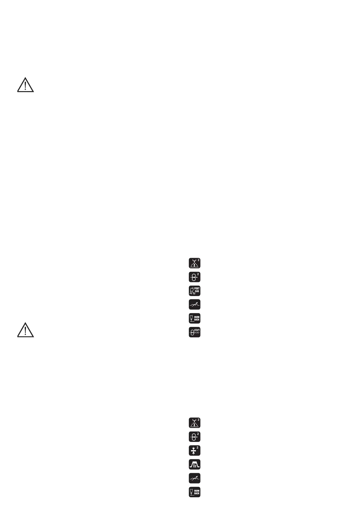
The user can customise the following welding parameters (Fig. L-2):
-
: welding voltage;
-
: wire feed speed;
-
: Post-gas. Use to adapt the protective gas outow starting from when
welding is stopped.
-
: Electronic reactance. A higher value determines a hotter welding bath;
-
: Burn-back. Use to adjust the wire burn-back time when welding is stopped;
-
: Soft-start. Use to adjust wire feed rate as welding starts, in order to optimise
arc strike.
The actual welding settings (wire speed, welding current and voltage) are shown in the
top section of the display.
7.1.1Settingofspoolgunparameters
In manual mode, the wire feeding speed and the welding voltage are adjusted
separately. The spool gun knob (Fig. L-5) adjusts the wire speed, whilst the welding
voltage is adjusted via the display.
7.2Synergicoperatingmode.
Synergic mode settings (Fig. L-3).
Press and hold the knob C-5 for at least 3 seconds to access the material, thread
diameter and gas type settings menu. (Fig. L-4). The welding machine sets itself
automatically in the best operation conditions established by the different synergy
curves that are saved. The user only has to select the material thickness to begin
welding.
The user can also customise the following welding parameters (Fig. L-5):
-
: Arc correction according to preset arc voltage.
-
: Wire feed speed.
-
: Material thickness.
-
: Welding current.
-
: Electronic reactance correction according to preset value.
-
: Burn-back correction. Use to correct the wire burn-back time when welding
is stopped in relation to the preset time.
 Loading...