Drive Module Replacement Kit
KIT NO. 9011905
Page1of7
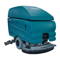
Model: 5680
9011904 Rev. 05 (04- 2018) Tennant Company www.tennantco.com
The original controller board p/n 397785 has been discontinued and replaced by this kit. The kit includes additional
parts for proper installation. Carefully follow the installation instructions as described below .
INSTALLATION INSTRUCTIONS:
Installation Time: 1.5 Hours
Spe c ia l Tools Re quir ed: Ohmmeter to adjust
potentiometer
FOR SAFETY: Before servicing machine, stop
on level surface, turn off machine, and
remove key.
1. Disconnect the black (- ) battery cable from
battery pack.
2. R em ov e the t w o screw s and the hei ght
adjustment knob from the control console housing.
Lower housing to access control board (Figure 1).
Fig. 1
3. Remove electrical cover from control board.
Discard cover, it’s not required with new module
(Figure 2).
Disconnect the wire connections from old board
and remove board from machine (two screws).
Discard old board (Figure 2).
Fig. 2
9011905 Kit Contents
Ref Part No. Description Qty.
1 1212548 Module, Drive [D5151 13] 1
2 1206698 Harness, Drive, Adapter [5680] 1
3 1213069 Harness, Potentiometer 1
4 392894 Gauge, Discharge, Battery, 36v, w/gasket 1
5 1073600 Screw, Pan, m4 x 0.7 x 25, fmg 2
1
4
3
5
2
4. Mount the new module to panel. Using a 9/64”
drill bit, drill the top mounting hole location as
described. For the bottom hole, use the module
as a drill template ( Figure 3).
Drill
bottom
hole
2
1
/
8
in
[54 mm]
8
1
/
4
in
[209.5 mm]
Attach
module
using
M4x25
Pan
Screw (2)
Old
board
hole
location
Drill top
hole
Use caution when drilling not to drill into tank.
Fig. 3