12
www.tescom-ups.gr
USER MANUAL
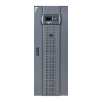
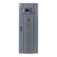
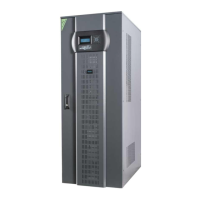
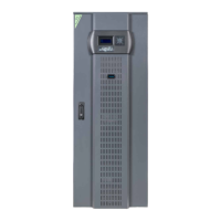
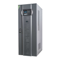
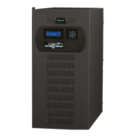
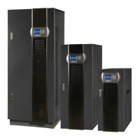
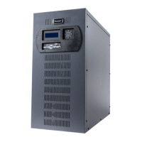
DS 300H Series � 3/3 � 30 kVA � UPS CONTROLLED UPS
II. UPS INSTALLATION
2.1 Introduction
WARNING!!!
• Do not apply electrical power to the UPS equipment before the arrival of authorized service
personnel.
• The UPS equipment should be installed only by qualified service personnel.
• The connection of the batteries and the maintenance should be done by qualified service
personnel.
• Do not make any short- circuit to the battery poles. Because of high voltage and high short-
circuit current, there is risk of electrical shock or burn.
• Eye protection should be worn to prevent injury from accidental electrical arcs. Remove rings,
watches and all metal objects. Only use tools with insulated handles. Wear rubber gloves.
This chapter contains location installation information of the UPS and the batteries. All the
establishments have their own specialties and needs. So in this part, the installation procedure is
not being explained step by step. Instead, general procedure and the applications are explained
for the technical personnel.
2.2 Unpacking
The UPS is packed and enclosed in a structural cardboard carton to protect it from damage.
1) Inspect for damage that may have occurred during the shipment If any damage is noted, call
the shipper immediately and retain the shipping carton and the UPS.
2) Carefully open the carton and take the UPS out.
3) Retain the carton and packing material for future use.
Unit package contents:
1) A user manual and Guarantee certificate.
2) Battery cabinet and/or shelf (Optional)
3) Battery connection cables.
2.3 Equipment Positioning
ATTENTION: Units are designed to operate on the concrete floor.
1. The equipmentʼs installation place must be an easy serving place.
2. Install the UPS in a protected area with adequate air flow and free of excessive dust.
3. You must therefore allow for a minimum gap of 250 mm behind the unit to allow adequate air
flow
4. Select a suitable place (temperature between 0°C and 40°C) and the relative humidity (%90
max)
5. It is recommended to place the equipment in an air-conditioned the room (24°C)
6. Temperature is a major factor in determining the battery life and capacity. Keep batteries away
from main heat sources or main air inlets etc.
7. In case of an operating the UPS in a dusty place, clean the air with a suitable air filtration
system.
8. Keep out of your equipment from explosive and flammable items.
9. Avoid direct sunlight, rain, and high humidity.
WARNING!!! Check the capacity of the forklift if it is available for lifting.
DO NOT LEAN OR LIFT THE UPS CABINET AFTER THE BATTERIES HAVE
11
2.4 Connecting the UPS Power Cables
WARNING!!! A separate power line should be used to supply the UPS AC input. Never use the
same line to supply another electrical device. Do not use any additional cable to
increase the length of the UPSʼs input cable. It is advised to use an MCCB suitable
for the input current on the UPSʼs input line.
The connection of the electrical panel should be supplied by a grounded outlet. Otherwise,
the UPS and the load connected to the output will be left ungrounded. The
grounding system must be checked, and must be strengthen if required. Potential
difference between ground and neutral must be less than 3V AC.
Descriptions of the UPS input output cable connection terminals are shown in figure 2.1
Recommended input line cable and fuse ratings are given in the table below.
UPS power
(kVA)
Recommended cable size (mm
2
)
Line input
Bypass input /
UPS output
External Battery
Input / output
Cable connections
U-V-W-N
Battery
connections
+ & -
10 10 10 6 16mm
2
terminal 16mm
2
terminal
15 10 10 10 16mm
2
terminal 16mm
2
terminal
20 10 10 10 16mm
2
terminal 16mm
2
terminal
30 16 16 16 16mm
2
terminal 16mm
2
terminal
NOTES: The neutral conductor should be sized for 1,5 times the output/bypass phase current. These
recommendations are for guideline purposes only and are superceded by local regulations
and codes of practice.
2.5 Safety Earth
The safety earth cable must be connected to the earth BUS BAR and bonded to each cabinet in
the system and also the earthing and neutral bonding arrangements must be in accordance with
the local laws.
ATTENTION!!! Failure to follow adequate earthing procedures can result in electric shock hazard to
personnel, or the risk of fire.
2.6 Cable connection procedure
WARNING!!! All connections of the UPS must be done by qualified service personnel
After positioning the UPS, the cables must be connected as described below:
1. Verify all switches and fuses in front of the UPS are at “0” position. (OFF)
2. Connect the 3 phase AC input coming from the mains distribution panel to the AC input terminals as
shown on the label. (Figure 2.1)
ATTENTION!!!: ENSURE CORRECT PHASE SEQUENCE.
If there is a phase sequence error, UPS doesnʼt transfer the load to INVERTER output. If
you canʼt see SYNC:OK in the INFORMATION MENU on LCD, then change the input phase sequence.
3. Connect the output of the UPS to the load distribution panel.
4. Connect the battery groups. Refer to battery installation section.