56
www.tescom-ups.gr
USER MANUAL
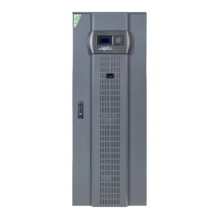
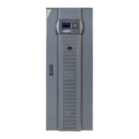
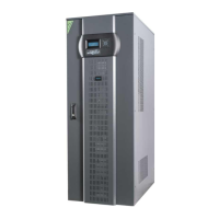
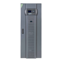
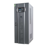
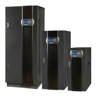
DS 300H Series � 3/3 � 30 kVA � UPS CONTROLLED UPS
54
VI. PARALLEL OPERATING INSTRUCTIONS
After all the electrical connections of UPS have been made and while all the circuit breakers and switchtes
of the device are turned OFF (at “0” position);
1. Check the polarities of battery connections:
K1 : + V (nominal voltage +360V, float charge voltage +405V)
K2-K2 : 0 V (common terminal for ʻʼ+ʼʼ and ʻʼ-ʻʼ battery groups)
K3 : - V (nominal voltage -360V, float charge voltage -405V)
2. Check 3-phase AC input and neutral connections (care should be taken fort he phase order).
ATTENTION!!! TWO CABLES FOR EACH BATTERY GROUP SHOULD BE USED FOR EXTERNAL
BATTERY CONNECTION, AND THE COMMON POINT CONNECTION SHOULD BE MADE ON K2
TERMİNAL BLOCK!
WARNING ! : UPS should never be operated without neutral connection.
3. Check the output load connections of UPS.
6.2.1 Starting UPSs from a completely shut down position:
1. Turn ON S1 (AC Input) switch (switch to ʻʼ1ʼʼ position)
2. Turn ON S2 (Bypass) switch (switch to ʻʼ1ʼʼ position)
3. Turn on S7 (On/Off) switch (to ʻʼ1ʼʼ position). LCD panel activates, and ʻʼINV RESET” or “PFC RESETʼʼ
message appears on the display meaning that the rectifier starts to operate.
4. Turn ON S4 (AC Output) switch (switch to ʻʼ1ʼʼ position)
5. A few seconds later red bypass light (L2) on front panel turns off and gren inverter light (L6) turns on.
L6 light indicates that the UPS has started normal operation and generating uninterruptable power for
the critical load.
6. Turn on S5 switch (to “1” position) to connect the battery group to UPS.
7. UPS is ready and in normal operation now.
6.2.2 Shutting down the UPS
After closing all the critical loads supplied by the UPSs output:
1. Turn off S4 (AC Output) switch (to ʻʼ0ʼʼ position).
2. Turn off S7 (On/Off) switch (to ʻʼ0ʼʼ position).
3. Turn off S5 (Battery) switch (to ʻʼ0ʼʼ position).
4. Turn off S2 (Bypass) switch (to ʻʼ0ʼʼ position).
5. Turn off S1 (AC Input) switch (to ʻʼ0ʼʼ position).
After performing the above procedure, UPSs is completetely shut-down. In this case PFC rectifier and
inverter is not operating and the batteries are not being charged.
6.2 OPERATING INSTRUCTIONS FOR PARALLEL CONNECTED UPSs.
55
6.2.3 Switching the UPS from a Normal Operation to Maintenance Bypass Condition
1. Enter COMMANDS menu by using UP and DOWN buttons on front panel during normal operation.
Select ENTER<BYPASS> command by using again the UP and DOWN buttons and pres ENTER
button. The critical load is transferred to bypass supply in this case and it is shown at LCD display with
“A09 MANUAL BYPASS” message. Besides L6 (load on UPS) light on front panel will be off and L2
light (bypass) will be on.
2. Turn on S3 (Maintenance Bypass) switch (after unlocking and taking away the padlock on it) to ʻʼ1ʼʼ
position.
3. Turn off S7, S5, S1, S2 and S4 switches (to ʻʼ0ʼʼ position).
In this case, bypass voltage is connected directly to the output of UPSs and the critical load is supplied via
maintenance bypass switch. No AC or DC supply is connected to the inside and the circuits of UPSs.
6.2.4 Switching the UPS from a Maintenance Bypass Condition to Normal Operation
1. Turn on S1 (AC Input) switch (to ʻʼ1ʼʼ position).
2. Turn on S2 (Bypass) switch (to ʻʼ1ʼʼ position).
3. Turn on S7 (On/Off) switch (to ʻʼ1ʼʼ position). LCD panel activates, and main menu will appear at the
display. Also “A08 ON MAINTENANCE” message shown and the inverter will not start yet.
4. Turn on S4 (AC Output) switch (to ʻʼ1ʼʼ position).
5. Turn off S3 (Maintenance Bypass) switch (to ʻʼ0ʼʼ position). Inverter will start automatically following the
turning off of S3 switch.
6. Connect the batteries by turning on S5 (Battery) switch (to ʻʼ1” position).
Now UPSs is ready for uninterruptable operation.