14
www.tescom-ups.gr
USER MANUAL
DS 300H Series � 3/3 � 30 kVA � UPS CONTROLLED UPS
WARNING :
- CHECK BOTH OF THE BATTERY GROUPS FOR CORRECT POLARITY AND VOLTAGE
- DO NOT TURN ON THE BATTERY SWITCH (F5) BEFORE STARTING THE UPS
5. Connect the copper earth bus, to the safety earth of the mains distribution panel.
NOTE : The earth and the neutral connections must be in accordance with the local rules.
WARNING: Note that the Input Neutral (N1) MUST also be connected to K10 terminal
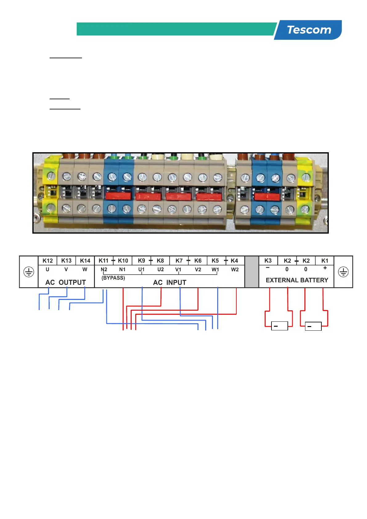
2.6.1 Description of connection terminals of the UPS :
• As shown on the power connection label of the UPS, U1, V1 and W1 phase of the incoming 3 phase
supply are used as the bypass inputs under normal conditions, if there is not a separate bypass supply
(split bypass).
• If there is a separate 3- phase AC supply for bypass (Split Bypass):
a-) Remove the links between K4 – K5, K6 – K7 and K8 – K9.
b-) Connect the phases of the bypass source U2, V2 and W2 to K5, K7 and K9 respectively.
c-) Connect the Neutral (N2) of the Bypass source to K11.
Note that the Neutral of the 3 phase input supply (N1) and the Neutral of the 3-phase bypass supply (N2)
must always be connected together to form the Neutral of the AC output.
10-15-20-30 kVA Cable Connection
(3 P+N AC)
Input
(3 P+N AC)
(3 P+N AC)
Battery
Group
Battery
Group
13
2.7 Battery Installation
WARNING!!! Be careful while connecting batteries.
ATTENTION!!! Open the battery switch/fuse before making any connection on the batteries.
The batteries associated with the UPS equipment are usually contained in a purpose-built battery cabinet.
In DS300H Series 10-15-20 and 30 KVA UPSs, there is enough space for 60 pieces of 12V 7Ah
maintenance free batteries.
Where battery racks are used, they should be sited and assembled in accordance with the battery
manufacturerʼs recommendations. In general, batteries require a well-ventilated, clean and dry environment
at reasonable temperatures to obtain efficient battery operation.
In general a minimum space of 10 mm must be left on all vertical sides of the battery block. A minimum
clearance of 20 mm should be allowed between the cell surface and any walls. All metal racks and cabinets
must be earthed.
2 Unpack each battery and check its terminal voltage with a suitable load. Any battery with terminal
voltage less than 10,5V must be charged before installation.
3 Please check the battery connecting hardware and documents. (cables, trays, connection diagrams)
4 Please locate suitable number of batteries on each rack, according to the battery installation and
connection diagram given with the unit.
5 Start locating the batteries from top to the bottom on the racks.
6 Be careful about the connection between the racks and polarities.
7 After interconnecting the batteries, connect “+”, “0” and “-“ leads of the batteries to the battery input
terminals on the UPS. Be careful to connect the batteries correctly and do not turn on (S5) before
checking all connections and before starting the UPS. In DS300H Series UPS, 60 blocks of batteries
are connected in series, in such a way that they form two strings of batteries with opposite polarity; with
a center tap connection to the NEUTRAL (N1-N2) internally.
NOTE THAT SEPARATE CABLES FROM EACH BATTERY GROUP SHOULD BE CONNECTED TO K2
TERMINALS TO FORM THE MIDPOINT CONNECTION.
WARNING!!! NEVER TURN ON S5 (BATTERY FUSE) WITHOUT CENTER POINT CONNECTION TO K2.